Information fuel-injection pump
BOSCH
9 410 614 189
9410614189
ZEXEL
106069-8030
1060698030
Rating:
Scheme ###:
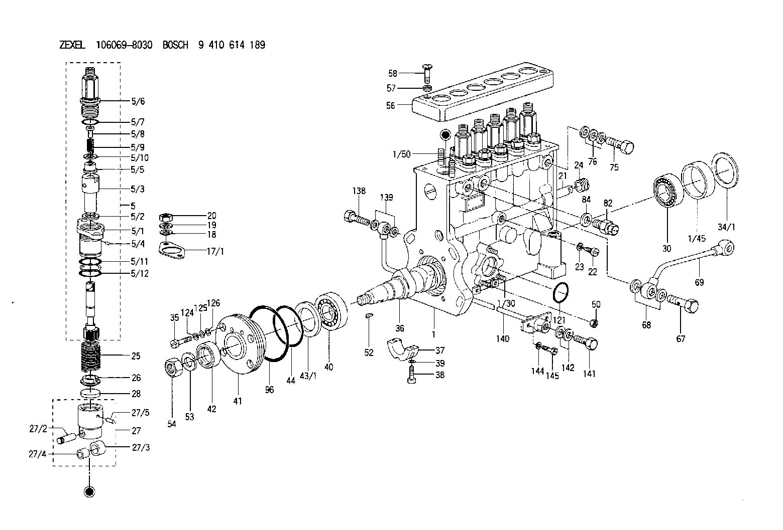
| 1. | [1] | 134000-8420 | PUMP HOUSING |
| 1/30. | [3] | 029040-6020 | STUD |
| 1/45. | [1] | 134311-0000 | SPACER RING |
| 1/50. | [12] | 029041-2100 | STUD |
| 5. | [6] | 134142-8920 | PLUNGER-AND-BARREL ASSY |
| 5/1. | [1] | 134131-1300 | FLANGE BUSHING |
| 5/2. | [1] | 029331-9040 | GASKET |
| 5/3. | [1] | 134101-9320 | PLUNGER-AND-BARREL ASSY |
| 5/4. | [1] | 134563-0600 | BEARING PIN |
| 5/5. | [1] | 134110-6220 | DELIVERY-VALVE ASSEMBLY |
| 5/6. | [1] | 134116-3020 | FITTING |
| 5/7. | [1] | 029632-5070 | O-RING |
| 5/8. | [1] | 134117-0500 | FILLER PIECE |
| 5/9. | [1] | 134112-2000 | COILED SPRING |
| 5/10. | [1] | 134115-0100 | GASKET |
| 5/11. | [1] | 029632-9030 | O-RING |
| 5/12. | [1] | 029632-9030 | O-RING |
| 17/1. | [0] | 134139-2400 | SHIM T0.15 |
| 17/1. | [0] | 134139-2500 | SHIM T0.4 |
| 17/1. | [0] | 134139-2600 | SHIM T0.5 |
| 17/1. | [0] | 134139-2700 | SHIM T0.6 |
| 17/1. | [0] | 134139-2800 | SHIM T0.7 |
| 17/1. | [0] | 134139-2900 | SHIM T0.8 |
| 17/1. | [0] | 134139-3000 | SHIM T0.9 |
| 17/1. | [0] | 134139-3100 | SHIM T1.0 |
| 18. | [12] | 029301-2330 | PLAIN WASHER |
| 19. | [12] | 014111-2440 | LOCKING WASHER D21.5&12.2T3 |
| 20. | [12] | 013021-2140 | UNION NUT M12P1.75H10 |
| 21. | [1] | 134256-2000 | CONTROL RACK |
| 22. | [1] | 134226-0000 | FLAT-HEAD SCREW |
| 23. | [1] | 134510-3900 | GASKET |
| 24. | [1] | 134222-0100 | BUSHING |
| 25. | [6] | 134215-0100 | COMPRESSION SPRING |
| 26. | [6] | 134217-0200 | SLOTTED WASHER |
| 27. | [6] | 134200-0520 | TAPPET |
| 27/2. | [1] | 134203-0100 | BEARING PIN |
| 27/3. | [1] | 134204-0100 | ROLLER |
| 27/4. | [1] | 134205-0000 | BUSHING |
| 27/5. | [1] | 134213-0000 | BEARING PIN |
| 28. | [6] | 134140-0400 | SPRING SEAT D14T3.9 |
| 30. | [1] | 016650-2230 | BEARING PLATE |
| 34/1. | [0] | 134303-0000 | SHIM D59.8&43T1.2 |
| 34/1. | [0] | 134303-0100 | SHIM D59.8&43T1.5 |
| 34/1. | [0] | 134303-0200 | SHIM D59.8&43T1.8 |
| 34/1. | [0] | 134303-0300 | SHIM D59.8&43T2.0 |
| 34/1. | [0] | 134303-0400 | SHIM D59.8&43T0.6 |
| 35. | [4] | 029050-6360 | FLAT-HEAD SCREW |
| 36. | [1] | 134371-3700 | CAMSHAFT |
| 37. | [1] | 134305-0000 | BEARING SHELL |
| 38. | [2] | 029020-6140 | HEX-SOCKET-HEAD CAP SCREW |
| 39. | [2] | 134510-3900 | GASKET |
| 40. | [1] | 016650-2230 | BEARING PLATE |
| 41. | [1] | 134316-0200 | COVER |
| 42. | [1] | 026712-5010 | PACKING RING |
| 43/1. | [0] | 134314-0000 | SHIM T0.1 |
| 43/1. | [0] | 134314-0100 | SHIM T0.12 |
| 43/1. | [0] | 134314-0200 | SHIM T0.14 |
| 43/1. | [0] | 134314-0300 | SHIM T0.16 |
| 43/1. | [0] | 134314-0400 | SHIM T0.18 |
| 43/1. | [0] | 134314-0500 | SHIM T0.3 |
| 43/1. | [0] | 134314-0600 | SHIM T0.5 |
| 44. | [1] | 029635-5010 | O-RING |
| 50. | [3] | 139206-0400 | UNION NUT |
| 52. | [1] | 025805-1910 | WOODRUFF KEY |
| 53. | [1] | 014111-8410 | LOCKING WASHER |
| 54. | [1] | 139218-0000 | UNION NUT |
| 56. | [1] | 134416-1500 | COVER |
| 57. | [2] | 014530-6540 | TAB WASHER |
| 58. | [2] | 021306-3940 | FLAT-HEAD SCREW |
| 67. | [1] | 029731-4680 | EYE BOLT |
| 68. | [2] | 029341-4130 | GASKET D20&13.8T2* |
| 69. | [1] | 134433-4720 | PIPE |
| 75. | [1] | 029731-4280 | EYE BOLT |
| 76. | [3] | 029341-4130 | GASKET D20&13.8T2* |
| 82. | [1] | 134420-0020 | BLEEDER SCREW |
| 84. | [1] | 026514-1840 | GASKET D17.9&14.2T1 |
| 96. | [1] | 029639-0020 | O-RING |
| 121. | [1] | 029633-1010 | O-RING |
| 124. | [4] | 029320-6010 | LOCKING WASHER |
| 125. | [4] | 029300-6170 | SHIM D12&6.2T1 |
| 126. | [4] | 029340-6120 | GASKET |
| 138. | [1] | 029731-4680 | EYE BOLT |
| 139. | [2] | 029341-4130 | GASKET D20&13.8T2* |
| 140. | [1] | 134433-1720 | PIPE |
| 141. | [1] | 029731-4680 | EYE BOLT |
| 142. | [2] | 029341-4130 | GASKET D20&13.8T2* |
| 144. | [2] | 014110-8440 | LOCKING WASHER |
| 145. | [2] | 010038-2040 | BLEEDER SCREW M8P1.25L20 |
Cross reference number
Zexel num
Bosch num
Firm num
Name
Information:
Indicator Lamps
The MECP indicator lamps provide the following status information:
"SUMMARY SHUTDOWN"
"SUMMARY ALARM"
"PLC FAILURE"
"ENGINE PRELUBE"The lamps activate when the "HORN SILENCE/LAMP TEST" switch is placed in the LAMP TEST.
Illustration 5 g00562727
"SUMMARY SHUTDOWN" Indicator Lamp
The "SUMMARY SHUTDOWN" lamp displays the status of the engine protection shutdown system.A red "SUMMARY SHUTDOWN" lamp indicates that a engine protection shutdown has occurred. The exact shutdown is annunciated on the PC window. A flashing "SUMMARY SHUTDOWN" lamp indicates an shutdown that is not acknowledged. A solid "SUMMARY SHUTDOWN" lamp indicates that the shutdown has been acknowledged.The cause of the shutdown is provided by the display screen. To acknowledge the indicator, turn the "HORN SILENCE/LAMP TEST" switch to the "HORN SILENCE" position. Correct the condition before restarting the engine. The control panel must be reset before the engine can be restarted. To reset the control panel, turn the "OFF/RESET, LOCAL, and REMOTE" switch to the "OFF/RESET" position. The air shutoff is activated for any shutdown. The air shutoff must also be reset before the engine can be restarted. If an overspeed shutdown occurs, the Engine Speed Switch must also be reset.Note: When a shutdown occurs the air damper closes. This secures the intake air. The air damper must be reset in order to start the engine. "SUMMARY ALARM" Indicator Lamp
The "SUMMARY ALARM" lamp provides a summary of the active MMS alarms. A red "SUMMARY ALARM" lamp indicates an alarm condition. Specific information on the alarm is provided on the PC window. A flashing "SUMMARY ALARM" lamp indicates an alarm that has not been acknowledged. A solid "SUMMARY ALARM" lamp indicates that the alarm has been acknowledged. The lamp will remain illuminated until the alarm condition is resolved."PLC FAILURE" Indicator Lamp
The "PLC FAILURE" lamp provides status of the PLC timer.The programmable logic control regularly sends a signal to a timer. If the timer fails to receive the signal, the yellow "PLC FAILURE" lamp illuminates. This indicates that the programmable logic control may not be providing full protection for the engine. Running the engine during abnormal conditions may cause engine damage.In the event of a PLC failure, the redundant relay logic shutdown system will provide minimum protection. The PLC failure should be corrected as soon as possible. While the "PLC FAILURE" lamp is illuminated the PC display may not be correct. Use the backup gauges for accurate information. If the programmable logic control is inoperative, the redundant shutdown system will provide minimum protection.PLC failure may be caused by the mode. Loss of the 24 Volt DC power may also cause a PLC failure. The system must be in the run mode.The "PLC FAILURE" lamp is illuminated and the "SUMMARY ALARM" lamp is flashing. Wait for five seconds. Count the number of flashes. The number of flashes corresponds to the slot that contains a faulty module."ENGINE PRELUBE" Indicator Lamp
The "ENGINE PRELUBE" lamp provides the status of engine lubrication.A green "ENGINE PRELUBE" lamp indicates that the engine is prelubed and that the engine is ready to start. Place the "PRELUBE-RUN-START"