Information fuel-injection pump
BOSCH
9 410 614 188
9410614188
ZEXEL
106069-8021
1060698021
Rating:
Scheme ###:
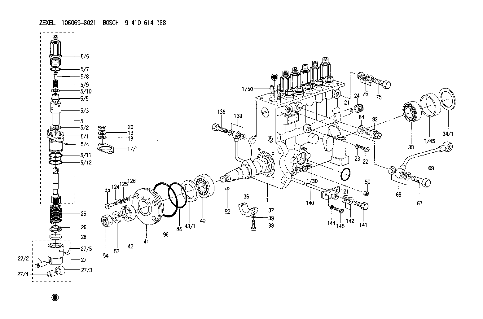
| 1. | [1] | 134000-8420 | PUMP HOUSING |
| 1/30. | [3] | 029040-6020 | STUD |
| 1/45. | [1] | 134311-0000 | SPACER RING |
| 1/50. | [12] | 029041-2100 | STUD |
| 5. | [6] | 134142-8920 | PLUNGER-AND-BARREL ASSY |
| 5/1. | [1] | 134131-1300 | FLANGE BUSHING |
| 5/2. | [1] | 029331-9040 | GASKET |
| 5/3. | [1] | 134101-9320 | PLUNGER-AND-BARREL ASSY |
| 5/4. | [1] | 134563-0600 | BEARING PIN |
| 5/5. | [1] | 134110-6220 | DELIVERY-VALVE ASSEMBLY |
| 5/6. | [1] | 134116-3020 | FITTING |
| 5/7. | [1] | 029632-5070 | O-RING |
| 5/8. | [1] | 134117-0500 | FILLER PIECE |
| 5/9. | [1] | 134112-2000 | COILED SPRING |
| 5/10. | [1] | 134115-0100 | GASKET |
| 5/11. | [1] | 029632-9030 | O-RING |
| 5/12. | [1] | 029632-9030 | O-RING |
| 17/1. | [0] | 134139-2400 | SHIM T0.15 |
| 17/1. | [0] | 134139-2500 | SHIM T0.4 |
| 17/1. | [0] | 134139-2600 | SHIM T0.5 |
| 17/1. | [0] | 134139-2700 | SHIM T0.6 |
| 17/1. | [0] | 134139-2800 | SHIM T0.7 |
| 17/1. | [0] | 134139-2900 | SHIM T0.8 |
| 17/1. | [0] | 134139-3000 | SHIM T0.9 |
| 17/1. | [0] | 134139-3100 | SHIM T1.0 |
| 18. | [12] | 029301-2330 | PLAIN WASHER |
| 19. | [12] | 014111-2440 | LOCKING WASHER D21.5&12.2T3 |
| 20. | [12] | 013021-2140 | UNION NUT M12P1.75H10 |
| 21. | [1] | 134256-2000 | CONTROL RACK |
| 22. | [1] | 134226-0000 | FLAT-HEAD SCREW |
| 23. | [1] | 134510-3900 | GASKET |
| 24. | [1] | 134222-0100 | BUSHING |
| 25. | [6] | 134215-0100 | COMPRESSION SPRING |
| 26. | [6] | 134217-0200 | SLOTTED WASHER |
| 27. | [6] | 134200-0120 | TAPPET |
| 27/2. | [1] | 134203-0100 | BEARING PIN |
| 27/3. | [1] | 134204-0000 | ROLLER |
| 27/4. | [1] | 134205-0000 | BUSHING |
| 27/5. | [1] | 134213-0000 | BEARING PIN |
| 28. | [6] | 134140-0400 | SPRING SEAT D14T3.9 |
| 30. | [1] | 016650-2230 | BEARING PLATE |
| 34/1. | [0] | 134303-0000 | SHIM D59.8&43T1.2 |
| 34/1. | [0] | 134303-0100 | SHIM D59.8&43T1.5 |
| 34/1. | [0] | 134303-0200 | SHIM D59.8&43T1.8 |
| 34/1. | [0] | 134303-0300 | SHIM D59.8&43T2.0 |
| 34/1. | [0] | 134303-0400 | SHIM D59.8&43T0.6 |
| 35. | [4] | 029050-6360 | FLAT-HEAD SCREW |
| 36. | [1] | 134371-3700 | CAMSHAFT |
| 37. | [1] | 134305-0000 | BEARING SHELL |
| 38. | [2] | 029020-6140 | HEX-SOCKET-HEAD CAP SCREW |
| 39. | [2] | 134510-3900 | GASKET |
| 40. | [1] | 016650-2230 | BEARING PLATE |
| 41. | [1] | 134316-2400 | COVER |
| 42. | [1] | 026712-5010 | PACKING RING |
| 43/1. | [0] | 134314-0000 | SHIM T0.1 |
| 43/1. | [0] | 134314-0100 | SHIM T0.12 |
| 43/1. | [0] | 134314-0200 | SHIM T0.14 |
| 43/1. | [0] | 134314-0300 | SHIM T0.16 |
| 43/1. | [0] | 134314-0400 | SHIM T0.18 |
| 43/1. | [0] | 134314-0500 | SHIM T0.3 |
| 43/1. | [0] | 134314-0600 | SHIM T0.5 |
| 44. | [1] | 029635-5010 | O-RING |
| 50. | [3] | 139206-0400 | UNION NUT |
| 52. | [1] | 025805-1910 | WOODRUFF KEY |
| 53. | [1] | 014111-8410 | LOCKING WASHER |
| 54. | [1] | 139218-0000 | UNION NUT |
| 67. | [1] | 029731-4680 | EYE BOLT |
| 68. | [2] | 029341-4130 | GASKET D20&13.8T2* |
| 69. | [1] | 134433-4720 | PIPE |
| 75. | [1] | 029731-4280 | EYE BOLT |
| 76. | [3] | 029341-4130 | GASKET D20&13.8T2* |
| 82. | [1] | 134420-0020 | BLEEDER SCREW |
| 84. | [1] | 026514-1840 | GASKET D17.9&14.2T1 |
| 96. | [1] | 029639-0020 | O-RING |
| 121. | [1] | 029633-1010 | O-RING |
| 124. | [4] | 029320-6010 | LOCKING WASHER |
| 125. | [4] | 029300-6170 | SHIM D12&6.2T1 |
| 126. | [4] | 029340-6120 | GASKET |
| 138. | [1] | 029731-4680 | EYE BOLT |
| 139. | [2] | 029341-4130 | GASKET D20&13.8T2* |
| 140. | [1] | 134433-1720 | PIPE |
| 141. | [1] | 029731-4680 | EYE BOLT |
| 142. | [2] | 029341-4130 | GASKET D20&13.8T2* |
| 144. | [2] | 014110-8440 | LOCKING WASHER |
| 145. | [2] | 010038-2040 | BLEEDER SCREW M8P1.25L20 |
Include in #1:
106692-4035
as FUEL INJECTION PUMP
Cross reference number
Zexel num
Bosch num
Firm num
Name
Information:
Problem 2
The engine does not crank.
Check the engine mounted start switch (EMSS).
Ensure that the emergency stop switch (ES) has been reset.
Place a switch across the terminals of the EMSS.
Close the switch momentarily, but do not start the engine.
Remove the switch when the test is completed. Result
The engine cranks.The EMSS is faulty or the circuit breaker (CB2) must be reset.
The engine does not crank.Go to Step 3.
Check the start/stop switch.
Ensure that the emergency stop switch (ES) has been reset.
Connect a switch with a 2 amp capacity between terminals (TS-21) and (TS-26) of the junction box.
Close the switch momentarily, but do not start the engine.
Disconnect the switch after the test is completed. Results
The engine cranks.The start/stop switch is faulty or the wiring to the switch is faulty. Replace the switch or repair the wiring. The circuit breaker (CB2) may need to be reset.
The engine does not crank.Go to Step 3.
Check the emergency stop switch (ES).
Ensure that the emergency stop switch (ES) has been reset.
Connect a switch with a 2 amp capacity between terminals (TS-26) and (TS-24) of the junction box.
Close the switch momentarily but do not start the engine.
Disconnect the switch after the test is completed. Result
The engine cranks.The emergency stop switch (ES) is faulty.
The engine does not crank.Reset the circuit breaker (CB5) and repeat Step 3. If the engine does not crank go to Step 4.
Check the components of the starting system.
Check the voltage at terminal (TS-24) of the junction box. Result
The voltage is low. Low voltage is between 1 volt and 20 volts.Charge the battery or repair the loose connections between the battery cable terminal and the battery. STOP.
The voltage is above 20 volts.The magnetic switch (MS), the pinion solenoid (PS), or the starting motor (SM) is faulty. The circuit breaker (CB2) may need to be reset. Reset the circuit breaker and repair the component that is faulty.
The voltage is zero (less than 1 volt).The circuit breaker (CB5) is being overloaded or the circuit breaker is faulty. Repair the short circuit or replace the circuit breaker. STOP.Problem 3
The engine starts and shutdown occurs immediately, or engine cranking terminates.
Check the protection switches.
Measure the voltage at terminal (SR2-30) while you crank the engine. Result
The voltage is above 10 volts while you crank the engine. The voltage then decreases to zero when the engine shuts down.The emergency stop switch (ES), the water temperature contactor switch (WTS), and the start/stop switch are opening. Check the start/stop switch first. The switch may be open across the common pair of contacts for the START/RUN switch when the switch is in the START position. The switch may also be open when the switch is released from the START position. Go to Step 7 of "Problem 1".
The voltage is above 10 volts at all times.The diode (D2) is faulty or there is a short across the diode circuit. The engine oil pressure switch (OPS1) may also have an intermittent short in the switch or in the connection. Refer