Information fuel-injection pump
BOSCH
9 410 610 283
9410610283
ZEXEL
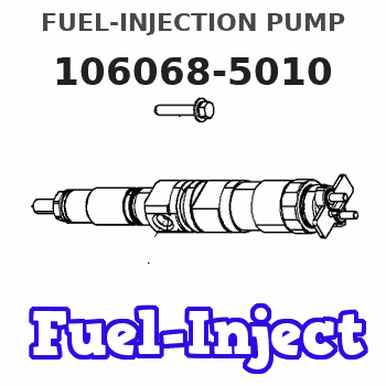
106068-5010
1060685010
Rating:
Scheme ###:
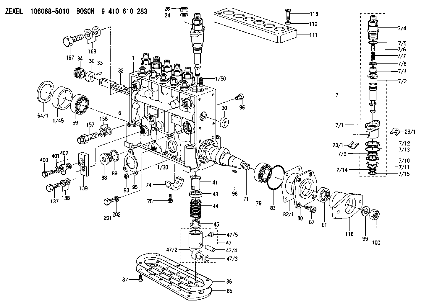
| 1. | [1] | 134050-3820 | PUMP HOUSING |
| 1/30. | [3] | 029040-6020 | STUD |
| 1/45. | [1] | 134311-0000 | SPACER RING |
| 1/50. | [12] | 134138-0000 | STUD |
| 6. | [1] | 131030-9320 | LEVEL INDICATOR |
| 7. | [6] | 134142-3320 | PLUNGER-AND-BARREL ASSY |
| 7/1. | [6] | 134131-1020 | FLANGE BUSHING |
| 7/2. | [6] | 134101-7520 | PLUNGER-AND-BARREL ASSY P59 |
| 7/3. | [6] | 134110-5220 | DELIVERY-VALVE ASSEMBLY P51 |
| 7/4. | [6] | 134116-1000 | FITTING |
| 7/5. | [6] | 139722-0400 | O-RING |
| 7/6. | [6] | 134117-0500 | FILLER PIECE |
| 7/7. | [6] | 132112-0200 | COILED SPRING |
| 7/8. | [6] | 134115-0100 | GASKET |
| 7/9. | [6] | 029302-0140 | PLAIN WASHER |
| 7/10. | [6] | 134135-0400 | CAPSULE |
| 7/11. | [6] | 029602-0010 | LOCKING WASHER |
| 7/12. | [6] | 134137-0000 | SPACER RING |
| 7/13. | [6] | 029632-9030 | O-RING |
| 7/14. | [6] | 139715-0400 | O-RING |
| 7/15. | [6] | 139715-0400 | O-RING |
| 23/1. | [0] | 134139-0000 | SHIM T0.5 |
| 23/1. | [0] | 134139-0000 | SHIM T0.5 |
| 23/1. | [0] | 134139-0100 | SHIM T0.6 |
| 23/1. | [0] | 134139-0200 | SHIM T0.7 |
| 23/1. | [0] | 134139-0300 | SHIM T0.8 |
| 23/1. | [0] | 134139-0400 | SHIM T0.9 |
| 23/1. | [0] | 134139-0500 | SHIM T0.4 |
| 23/1. | [0] | 134139-0600 | SHIM T0.15 |
| 23/1. | [0] | 134139-2300 | SHIM T1.5 |
| 24. | [12] | 134132-0300 | PLAIN WASHER |
| 26. | [12] | 013021-0040 | UNION NUT M10P1.5H8 |
| 30. | [2] | 134001-0000 | BUSHING |
| 30. | [2] | 134001-0000 | BUSHING |
| 32. | [1] | 134256-2401 | CONTROL RACK |
| 33. | [1] | 024030-2030 | BEARING PIN |
| 34. | [1] | 134222-0000 | BUSHING |
| 41. | [6] | 134241-0021 | CONTROL SLEEVE |
| 43. | [6] | 134216-0000 | SLOTTED WASHER |
| 44. | [6] | 134215-0200 | COMPRESSION SPRING |
| 45. | [6] | 134217-0500 | SLOTTED WASHER |
| 47. | [6] | 134200-0020 | TAPPET |
| 47/2. | [6] | 134204-0000 | ROLLER |
| 47/3. | [6] | 134205-0000 | BUSHING |
| 47/4. | [6] | 134203-0000 | BEARING PIN |
| 47/5. | [6] | 131206-0500 | SLIDER |
| 59. | [1] | 016650-2230 | BEARING PLATE 4T-32205(NSK) |
| 59B. | [1] | 028222-5010 | BEARING PLATE 32205-N(KOYO) |
| 64/1. | [0] | 134303-0000 | SHIM D59.8&43T1.2 |
| 64/1. | [0] | 134303-0100 | SHIM D59.8&43T1.5 |
| 64/1. | [0] | 134303-0200 | SHIM D59.8&43T1.8 |
| 64/1. | [0] | 134303-0300 | SHIM D59.8&43T2.0 |
| 64/1. | [0] | 134303-0400 | SHIM D59.8&43T0.6 |
| 67. | [4] | 029010-6810 | BLEEDER SCREW |
| 71. | [1] | 134371-2500 | CAMSHAFT |
| 74. | [1] | 134306-0000 | BEARING SHELL |
| 75. | [2] | 020106-2040 | BLEEDER SCREW |
| 79. | [1] | 016650-2230 | BEARING PLATE 4T-32205(NSK) |
| 79B. | [1] | 028222-5010 | BEARING PLATE 32205-N(KOYO) |
| 80. | [1] | 134316-0700 | COVER |
| 81. | [1] | 026712-5010 | PACKING RING |
| 82/1. | [0] | 134314-0000 | SHIM T0.1 |
| 82/1. | [0] | 134314-0100 | SHIM T0.12 |
| 82/1. | [0] | 134314-0200 | SHIM T0.14 |
| 82/1. | [0] | 134314-0300 | SHIM T0.16 |
| 82/1. | [0] | 134314-0400 | SHIM T0.18 |
| 82/1. | [0] | 134314-0500 | SHIM T0.3 |
| 82/1. | [0] | 134314-0600 | SHIM T0.5 |
| 83. | [1] | 029635-5010 | O-RING |
| 85. | [1] | 134043-0800 | COVER |
| 86. | [1] | 134042-1400 | GASKET |
| 87. | [12] | 012206-1640 | FLAT-HEAD SCREW |
| 88. | [1] | 134045-0100 | CAPSULE |
| 89. | [1] | 026524-2940 | GASKET |
| 93. | [3] | 139206-0400 | UNION NUT |
| 95. | [1] | 131041-0800 | GASKET |
| 96. | [6] | 134047-0000 | CAPSULE |
| 98. | [1] | 025805-1910 | WOODRUFF KEY |
| 99. | [1] | 023641-8410 | LOCKING WASHER |
| 100. | [1] | 134325-0700 | UNION NUT |
| 111. | [1] | 134416-0100 | COVER |
| 112. | [2] | 014530-6540 | TAB WASHER |
| 113. | [2] | 021306-3010 | FLAT-HEAD SCREW |
| 116. | [1] | 156635-7900 | COUPLING PLATE |
| 137. | [1] | 134430-0420 | EYE BOLT |
| 138. | [2] | 029331-4230 | GASKET |
| 139. | [1] | 133431-0820 | CONNECTOR |
| 157. | [1] | 131424-1520 | OVER FLOW VALVE |
| 158. | [2] | 029331-4230 | GASKET |
| 159. | [1] | 139814-0700 | INLET UNION |
| 167. | [1] | 029731-4680 | EYE BOLT |
| 168. | [2] | 029331-4230 | GASKET |
| 169. | [1] | 139814-0700 | INLET UNION |
| 201. | [1] | 029111-0020 | CAPSULE |
| 202. | [1] | 026510-1440 | GASKET |
| 400. | [1] | 029731-2230 | EYE BOLT |
| 401. | [2] | 026512-1540 | GASKET |
| 402. | [1] | 027112-0840 | INLET UNION |
Include in #1:
106682-4032
as FUEL INJECTION PUMP
Cross reference number
Zexel num
Bosch num
Firm num
Name
FUEL-INJECTION PUMP
* Q 14CA FUEL INJECTION PUMP PE6P,6PD PE
* Q 14CA FUEL INJECTION PUMP PE6P,6PD PE
Information:
(1) Maximum permissible temperature of the gear for installation on the camshaft (do not use a torch) ... 315°C (600°F)(2) Tight fit between the gear and camshaft ... 0.037 to 0.123 mm (.0015 to .0048 in)(3) Diameter of the surfaces (journals) for the camshaft bearings (new) ... 69.850 0.013 mm (2.7500 .0005 in) Bore in front bearing for the camshaft (after assembly) ... 69.969 0.048 mm (2.7547 .0019 in)Bore in the other six bearings for the camshaft (after assembly) ... 69.982 0.061 mm (2.7552 .0024 in)(4) Thickness of thrust plate (new) ... 4.65 0.03 mm (.183 .001 in) End play of the camshaft ... 0.10 to 0.26 mm (.004 to .010 in) (5) Height of camshaft lobes.To find lobe height, use the procedure that follows:A. Measure camshaft lobe height (5).B. Measure base circle (7).C. Subtract base circle (STEP B) from lobe height (STEP A). The difference is actual lobe lift (6).D. Specified camshaft lobe lift (6) is:4W2430 Camshaft Assembly
a. Exhaust lobe ... 10.211 mm (.4020 in)b. Intake lobe ... 10.211 mm (.4020 in)7W3797 Camshaft Assembly
a. Exhaust lobe ... 10.210 mm (.4019 in)b. Intake lobe ... 10.212 mm (.4021 in)Maximum permissible difference between actual lobe lift (STEP C) and specified lobe lift (STEP D) is 0.13 mm (.005 in).Intake Valve Timing
1. Check the No. 1 intake valve lash with the engine stopped. The valve lash must be 0.30 to 0.46 mm (.012 to .018 in). If the valve lash is not in this range, adjust the lash to 0.38 mm (.015 in).2. Mark Top Center Position of the crankshaft on the vibration damper or pulley.3. Use a dial indicator to measure the intake valve movement.4. Rotate the crankshaft in the direction of normal engine rotation. Stop when the intake valve is 1.91 mm (.075 in) off its seat in the opening sequence.At this point the crankshaft Top Center Position Mark must be in position as follows: Engines with the 4W2430 Camshaft Assembly ... 7 2° After Top CenterEngines with the 7W3797 Camshaft Assembly ... 1 2° After Top CenterChecking Valve-Camshaft Timing (field procedure)
The following procedure will simplify the checking of the camshaft timing procedures.1. Set the No. 3 intake bridge adjustment.2. Set the No. 3 intake valve lash.3. Install the bolt in the flywheel with No. 1 piston at top center.4. Install the dial indicator (magnetic base) to No. 3 intake bridge.5. Remove the bolt from the flywheel.6. Set the gauge at zero and rotate the engine in the normal direction of operation (counterclockwise as seen from the flywheel end) until dial travel stops.The following chart indicates the correct setting.