Information fuel-injection pump
BOSCH
9 410 613 569
9410613569
ZEXEL
106068-3801
1060683801
Rating:
Scheme ###:
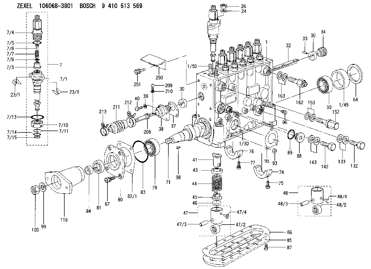
| 1. | [1] | 134070-2420 | PUMP HOUSING |
| 1/30. | [3] | 029040-6020 | STUD |
| 1/45. | [1] | 134311-0000 | SPACER RING |
| 1/50. | [12] | 134138-0100 | STUD |
| 7. | [6] | 134147-7420 | PLUNGER-AND-BARREL ASSY |
| 7/1. | [1] | 134173-3620 | PLUNGER-AND-BARREL ASSY |
| 7/3. | [1] | 134160-1920 | DELIVERY-VALVE ASSEMBLY |
| 7/4. | [1] | 134171-0120 | FITTING |
| 7/5. | [1] | 016500-1850 | O-RING |
| 7/6. | [1] | 134117-1700 | FILLER PIECE |
| 7/7. | [1] | 134112-3500 | COMPRESSION SPRING |
| 7/8. | [1] | 134115-0300 | GASKET |
| 7/10. | [1] | 134135-0300 | CAPSULE |
| 7/11. | [1] | 029602-0010 | LOCKING WASHER |
| 7/13. | [1] | 139727-0300 | O-RING |
| 7/14. | [1] | 139715-0300 | O-RING |
| 7/15. | [1] | 139715-0300 | O-RING |
| 23/1. | [0] | 139400-0900 | SHIM T0.500 |
| 23/1. | [0] | 139400-1000 | SHIM T0.525 |
| 23/1. | [0] | 139400-1100 | SHIM T0.550 |
| 23/1. | [0] | 139400-1200 | SHIM T0.575 |
| 23/1. | [0] | 139400-1200 | SHIM T0.575 |
| 23/1. | [0] | 139400-1300 | SHIM T0.600 |
| 23/1. | [0] | 139400-1400 | SHIM T0.625 |
| 23/1. | [0] | 139400-1500 | SHIM T0.650 |
| 23/1. | [0] | 139400-1600 | SHIM T0.675 |
| 23/1. | [0] | 139400-1700 | SHIM T0.700 |
| 23/1. | [0] | 139400-1800 | SHIM T0.725 |
| 23/1. | [0] | 139400-1900 | SHIM T0.750 |
| 23/1. | [0] | 139400-2000 | SHIM T0.775 |
| 23/1. | [0] | 139400-2100 | SHIM T0.800 |
| 23/1. | [0] | 139400-2200 | SHIM T0.825 |
| 23/1. | [0] | 139400-2300 | SHIM T0.850 |
| 23/1. | [0] | 139400-2400 | SHIM T0.875 |
| 23/1. | [0] | 139400-2500 | SHIM T0.900 |
| 23/1. | [0] | 139400-2600 | SHIM T0.925 |
| 23/1. | [0] | 139400-2700 | SHIM T0.950 |
| 23/1. | [0] | 139400-2800 | SHIM T0.975 |
| 23/1. | [0] | 139400-2900 | SHIM T1.000 |
| 23/1. | [0] | 139400-3000 | SHIM T1.025 |
| 23/1. | [0] | 139400-3100 | SHIM T1.050 |
| 23/1. | [0] | 139400-3200 | SHIM T1.075 |
| 23/1. | [0] | 139400-3300 | SHIM T1.100 |
| 23/1. | [0] | 139400-3400 | SHIM T1.125 |
| 23/1. | [0] | 139400-3500 | SHIM T1.150 |
| 23/1. | [0] | 139400-3600 | SHIM T1.175 |
| 23/1. | [0] | 139400-3700 | SHIM T1.200 |
| 23/1. | [0] | 139400-3800 | SHIM T1.225 |
| 23/1. | [0] | 139400-3900 | SHIM T1.250 |
| 23/1. | [0] | 139400-4000 | SHIM T1.275 |
| 23/1. | [0] | 139400-4100 | SHIM T1.300 |
| 23/1. | [0] | 139400-4200 | SHIM T1.325 |
| 23/1. | [0] | 139400-4300 | SHIM T1.350 |
| 23/1. | [0] | 139400-4400 | SHIM T1.375 |
| 23/1. | [0] | 139400-4500 | SHIM T1.400 |
| 23/1. | [0] | 139400-4600 | SHIM T1.425 |
| 23/1. | [0] | 139400-4700 | SHIM T1.450 |
| 23/1. | [0] | 139400-4800 | SHIM T1.475 |
| 23/1. | [0] | 139400-4900 | SHIM T1.500 |
| 23/1. | [0] | 139400-5000 | SHIM T1.525 |
| 23/1. | [0] | 139400-5100 | SHIM T1.550 |
| 23/1. | [0] | 139400-5200 | SHIM T1.575 |
| 23/1. | [0] | 139400-5300 | SHIM T1.600 |
| 23/1. | [0] | 139400-5400 | SHIM T1.625 |
| 23/1. | [0] | 139400-5500 | SHIM T1.650 |
| 23/1. | [0] | 139400-5600 | SHIM T1.675 |
| 23/1. | [0] | 139400-5700 | SHIM T1.700 |
| 23/1. | [0] | 139400-5800 | SHIM T1.725 |
| 23/1. | [0] | 139400-5900 | SHIM T1.750 |
| 23/1. | [0] | 139400-6000 | SHIM T1.775 |
| 23/1. | [0] | 139400-6100 | SHIM T1.800 |
| 23/1. | [0] | 139400-6200 | SHIM T1.825 |
| 23/1. | [0] | 139400-6300 | SHIM T1.850 |
| 23/1. | [0] | 139400-6400 | SHIM T1.875 |
| 23/1. | [0] | 139400-6500 | SHIM T1.900 |
| 23/1. | [0] | 139400-6600 | SHIM T1.925 |
| 23/1. | [0] | 139400-6700 | SHIM T1.950 |
| 23/1. | [0] | 139400-6800 | SHIM T1.975 |
| 24. | [12] | 134132-0300 | PLAIN WASHER D20&11T2.5 |
| 26. | [12] | 139210-0200 | UNION NUT |
| 30. | [2] | 134001-0400 | BUSHING |
| 30. | [2] | 134001-0400 | BUSHING |
| 32. | [1] | 134256-5500 | CONTROL RACK |
| 33. | [1] | 024030-2030 | BEARING PIN |
| 34. | [1] | 134222-0000 | BUSHING |
| 37. | [1] | 134510-6800 | GASKET |
| 38. | [1] | 134222-1300 | ADAPTOR |
| 39. | [4] | 014110-4440 | LOCKING WASHER |
| 40. | [4] | 012154-1440 | FLAT-HEAD SCREW M4P0.7L14 |
| 41. | [6] | 134241-0620 | CONTROL SLEEVE |
| 43. | [6] | 134216-0000 | SLOTTED WASHER |
| 44. | [6] | 134215-0800 | COMPRESSION SPRING |
| 45. | [6] | 134217-0700 | SLOTTED WASHER |
| 46. | [6] | 134563-2700 | SPRING SEAT |
| 47. | [4] | 134200-0820 | TAPPET |
| 47/2. | [1] | 134204-0200 | ROLLER |
| 47/3. | [1] | 134203-0000 | BEARING PIN |
| 47/4. | [1] | 131206-0500 | SLIDER |
| 48. | [2] | 134200-0720 | TAPPET |
| 48/2. | [1] | 134204-0200 | ROLLER |
| 48/3. | [1] | 134203-0000 | BEARING PIN |
| 48/4. | [1] | 131206-0500 | SLIDER |
| 59. | [1] | 016650-2230 | BEARING PLATE |
| 64. | [1] | 134303-0500 | SHIM D59.8&43T1.6 |
| 67. | [4] | 139006-4200 | BLEEDER SCREW |
| 71. | [1] | 134340-1500 | CAMSHAFT |
| 74. | [1] | 134306-1000 | BEARING SHELL |
| 75. | [2] | 020106-2040 | BLEEDER SCREW M6P1L20 |
| 76. | [2] | 134306-1100 | BEARING SHELL |
| 77. | [4] | 020106-2040 | BLEEDER SCREW M6P1L20 |
| 79. | [1] | 035302-0600 | BEARING PLATE |
| 80. | [1] | 134316-3300 | COVER |
| 81. | [1] | 139634-0200 | PACKING RING |
| 82/1. | [0] | 134314-0700 | SHIM T0.1 |
| 82/1. | [0] | 134314-0800 | SHIM T0.12 |
| 82/1. | [0] | 134314-0900 | SHIM T0.14 |
| 82/1. | [0] | 134314-1000 | SHIM T0.16 |
| 82/1. | [0] | 134314-1100 | SHIM T0.18 |
| 82/1. | [0] | 134314-1200 | SHIM T0.3 |
| 82/1. | [0] | 134314-1300 | SHIM T0.5 |
| 83. | [1] | 139766-0000 | O-RING |
| 84. | [1] | 134563-2500 | SLIDING PIECE |
| 85. | [1] | 134043-0800 | COVER |
| 86. | [1] | 134042-1400 | GASKET |
| 87. | [12] | 012206-1640 | FLAT-HEAD SCREW M6P1L16 |
| 88. | [1] | 134045-0100 | CAPSULE |
| 89. | [1] | 026524-2940 | GASKET D28.9&24.3T2 |
| 93. | [3] | 139206-0400 | UNION NUT |
| 95. | [1] | 131041-0800 | GASKET |
| 96. | [6] | 134047-0000 | CAPSULE |
| 98. | [1] | 025806-2210 | WOODRUFF KEY |
| 99. | [1] | 014112-0440 | LOCKING WASHER |
| 100. | [1] | 023012-0040 | UNION NUT M20P1.5H16 |
| 116. | [1] | 156643-5300 | COUPLING PLATE |
| 132. | [1] | 029731-4680 | EYE BOLT |
| 133. | [2] | 029341-4130 | GASKET D20&13.8T2* |
| 142. | [1] | 029731-0120 | EYE BOLT |
| 143. | [2] | 029341-0110 | GASKET |
| 152. | [1] | 131425-1620 | OVER FLOW VALVE |
| 153. | [2] | 029341-4130 | GASKET D20&13.8T2* |
| 162. | [1] | 131401-0120 | EYE BOLT |
| 163. | [2] | 029341-4130 | GASKET D20&13.8T2* |
| 208. | [1] | 134563-4000 | CONNECTOR |
| 209. | [2] | 010635-1040 | FLAT-HEAD SCREW M5P0.8L10 |
| 210. | [2] | 014110-5440 | LOCKING WASHER |
| 211. | [1] | 134563-4200 | COVER |
| 212. | [1] | 134563-4300 | CLAMPING BAND |
| 213. | [1] | 134563-3700 | CLAMPING BAND |
| 250. | [1] | 134563-8320 | BRACKET |
| 251. | [2] | 029010-6810 | BLEEDER SCREW |
Cross reference number
Zexel num
Bosch num
Firm num
Name
Information:
Typical Example1. Disconnect wire (1) from Jake Brake. Remove three bolts (2) and remove the Jake Brake.
Typical Example2. Remove Jake Brake exhaust bridge assemblies (3). The following steps are for the installation of the Jake Brake.3. Install Jake Brake exhaust bridge assemblies (3) in the same orientation as illustrated.4. Position Jake Brake assembly and install bolts (2). Connect wire (1).End By:a. install valve cover assemblies as they are illustrated.Disassemble & Assemble Jake Brake
Remove the control valve and slave piston carefully. Control valves are under load from the control valve springs. The slave piston is retained by springs that are under heavy compression. Remove with care to avoid injury.
Start By:a. remove Jake Brake 1. Apply finger pressure to the control valve cover (2). Rotate retaining ring (1) to the slot in the housing. Remove the retaining ring. Release finger pressure slowly. Remove insert (3), spring (4), spring (5), collar (6) and control valve (7).2. Remove solenoid valve (8). Remove three O-ring seals (9) from housing.3. Remove locknut (11). Back out adjusting screw (10) until slave piston is fully retracted.4. Clamp and depress retainer (18) until retainer is 1 mm (.030 in) below the retaining ring groove. Remove retaining ring (19). Back out clamp until springs are loose. Remove clamp. Remove retainer (18), spring (17), spring (16) and slave piston (15).5. Remove anti-rotation pin (13) and washer (12). Remove master piston assembly (14).The following steps are for the assembly of the Jake Brake.6. Inspect master piston assembly (14) for damage. The piston surface must be free of score or wear marks. The piston must move freely in the housing bore. Inspect the spring to insure it is not broken.7. Compress the return spring in the master piston assembly with a pick or probe. While compressed, insert a small pin into the access hole and remove pick or probe. Insert the master piston assembly. Install anti-rotation pin (13) and washer (12) into the housing and remove small pin. The return spring will then be retained by the anti-rotation pin.8. Install slave piston (15), spring (16), spring (17), and retainer (18). Clamp and compress the slave piston retainer until retainer is about 1 mm (.030 in) below the retaining ring groove. Install retaining ring (19). Release clamp.9. Screw adjusting screw (12) in until touching slave piston assembly. Install locknut (11).10. Check the O-ring seals for the solenoid valve for wear or damage. Replace as required. Install three O-ring seals (9) on the solenoid valve. Install solenoid valve (8). Tighten the solenoid to a torque of 7 N m (60 lb in). Be sure O-ring seals are seated properly. Be careful not to twist or unseat O-ring seals while installing.11. Install control valve (7). Install collar (6) with longer sleeve area up. Install spring (4), spring (5), retainer (3) and control valve cover (2). Depress control valve cover with finger. Install retaining ring (1). Rotate retaining ring so the retaining ring ears are located away from the slot in the housing. Release finger