Information fuel-injection pump
BOSCH
9 410 612 472
9410612472
ZEXEL
106068-3540
1060683540
Rating:
Scheme ###:
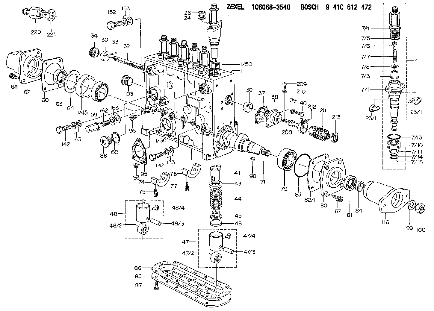
| 1. | [1] | 134070-0520 | PUMP HOUSING |
| 1/30. | [3] | 029040-6020 | STUD |
| 1/45. | [1] | 134311-0000 | SPACER RING |
| 1/50. | [12] | 134138-0100 | STUD |
| 7. | [6] | 134147-9620 | PLUNGER-AND-BARREL ASSY |
| 7/1. | [1] | 134173-0220 | PLUNGER-AND-BARREL ASSY |
| 7/3. | [1] | 134160-1920 | DELIVERY-VALVE ASSEMBLY |
| 7/4. | [1] | 134171-0120 | FITTING |
| 7/5. | [1] | 016500-1850 | O-RING |
| 7/6. | [1] | 134117-1700 | FILLER PIECE |
| 7/7. | [1] | 134112-4100 | COMPRESSION SPRING |
| 7/8. | [1] | 134115-0300 | GASKET |
| 7/10. | [1] | 134135-0300 | CAPSULE |
| 7/11. | [1] | 029602-0010 | LOCKING WASHER |
| 7/13. | [1] | 139727-0300 | O-RING |
| 7/14. | [1] | 139715-0300 | O-RING |
| 7/15. | [1] | 139715-0300 | O-RING |
| 23/1. | [0] | 139400-0900 | SHIM T0.500 |
| 23/1. | [0] | 139400-0900 | SHIM T0.500 |
| 23/1. | [0] | 139400-1000 | SHIM T0.525 |
| 23/1. | [0] | 139400-1100 | SHIM T0.550 |
| 23/1. | [0] | 139400-1200 | SHIM T0.575 |
| 23/1. | [0] | 139400-1300 | SHIM T0.600 |
| 23/1. | [0] | 139400-1400 | SHIM T0.625 |
| 23/1. | [0] | 139400-1500 | SHIM T0.650 |
| 23/1. | [0] | 139400-1600 | SHIM T0.675 |
| 23/1. | [0] | 139400-1700 | SHIM T0.700 |
| 23/1. | [0] | 139400-1800 | SHIM T0.725 |
| 23/1. | [0] | 139400-1900 | SHIM T0.750 |
| 23/1. | [0] | 139400-2000 | SHIM T0.775 |
| 23/1. | [0] | 139400-2100 | SHIM T0.800 |
| 23/1. | [0] | 139400-2200 | SHIM T0.825 |
| 23/1. | [0] | 139400-2300 | SHIM T0.850 |
| 23/1. | [0] | 139400-2400 | SHIM T0.875 |
| 23/1. | [0] | 139400-2500 | SHIM T0.900 |
| 23/1. | [0] | 139400-2600 | SHIM T0.925 |
| 23/1. | [0] | 139400-2700 | SHIM T0.950 |
| 23/1. | [0] | 139400-2800 | SHIM T0.975 |
| 23/1. | [0] | 139400-2900 | SHIM T1.000 |
| 23/1. | [0] | 139400-3000 | SHIM T1.025 |
| 23/1. | [0] | 139400-3100 | SHIM T1.050 |
| 23/1. | [0] | 139400-3200 | SHIM T1.075 |
| 23/1. | [0] | 139400-3300 | SHIM T1.100 |
| 23/1. | [0] | 139400-3400 | SHIM T1.125 |
| 23/1. | [0] | 139400-3500 | SHIM T1.150 |
| 23/1. | [0] | 139400-3600 | SHIM T1.175 |
| 23/1. | [0] | 139400-3700 | SHIM T1.200 |
| 23/1. | [0] | 139400-3800 | SHIM T1.225 |
| 23/1. | [0] | 139400-3900 | SHIM T1.250 |
| 23/1. | [0] | 139400-4000 | SHIM T1.275 |
| 23/1. | [0] | 139400-4100 | SHIM T1.300 |
| 23/1. | [0] | 139400-4200 | SHIM T1.325 |
| 23/1. | [0] | 139400-4300 | SHIM T1.350 |
| 23/1. | [0] | 139400-4400 | SHIM T1.375 |
| 23/1. | [0] | 139400-4500 | SHIM T1.400 |
| 23/1. | [0] | 139400-4600 | SHIM T1.425 |
| 23/1. | [0] | 139400-4700 | SHIM T1.450 |
| 23/1. | [0] | 139400-4800 | SHIM T1.475 |
| 23/1. | [0] | 139400-4900 | SHIM T1.500 |
| 23/1. | [0] | 139400-5000 | SHIM T1.525 |
| 23/1. | [0] | 139400-5100 | SHIM T1.550 |
| 23/1. | [0] | 139400-5200 | SHIM T1.575 |
| 23/1. | [0] | 139400-5300 | SHIM T1.600 |
| 23/1. | [0] | 139400-5400 | SHIM T1.625 |
| 23/1. | [0] | 139400-5500 | SHIM T1.650 |
| 23/1. | [0] | 139400-5600 | SHIM T1.675 |
| 23/1. | [0] | 139400-5700 | SHIM T1.700 |
| 23/1. | [0] | 139400-5800 | SHIM T1.725 |
| 23/1. | [0] | 139400-5900 | SHIM T1.750 |
| 23/1. | [0] | 139400-6000 | SHIM T1.775 |
| 23/1. | [0] | 139400-6100 | SHIM T1.800 |
| 23/1. | [0] | 139400-6200 | SHIM T1.825 |
| 23/1. | [0] | 139400-6300 | SHIM T1.850 |
| 23/1. | [0] | 139400-6400 | SHIM T1.875 |
| 23/1. | [0] | 139400-6500 | SHIM T1.900 |
| 23/1. | [0] | 139400-6600 | SHIM T1.925 |
| 23/1. | [0] | 139400-6700 | SHIM T1.950 |
| 23/1. | [0] | 139400-6800 | SHIM T1.975 |
| 24. | [12] | 134132-0300 | PLAIN WASHER D20&11T2.5 |
| 26. | [12] | 139210-0200 | UNION NUT |
| 30. | [2] | 134001-0500 | BUSHING |
| 30. | [2] | 134001-0500 | BUSHING |
| 32. | [1] | 134256-3800 | CONTROL RACK |
| 33. | [1] | 024030-2030 | BEARING PIN |
| 34. | [1] | 134222-0000 | BUSHING |
| 37. | [1] | 134510-6800 | GASKET |
| 38. | [1] | 134222-1400 | ADAPTOR |
| 39. | [4] | 014110-4440 | LOCKING WASHER |
| 40. | [4] | 012154-1440 | FLAT-HEAD SCREW M4P0.7L14 |
| 41. | [6] | 134241-0620 | CONTROL SLEEVE |
| 43. | [6] | 134216-0000 | SLOTTED WASHER |
| 44. | [6] | 134215-0800 | COMPRESSION SPRING |
| 45. | [6] | 134217-0700 | SLOTTED WASHER |
| 46. | [6] | 134563-2700 | SPRING SEAT |
| 47. | [4] | 134200-0820 | TAPPET |
| 47/2. | [1] | 134204-0200 | ROLLER |
| 47/3. | [1] | 134203-0000 | BEARING PIN |
| 47/4. | [1] | 131206-0500 | SLIDER |
| 48. | [2] | 134200-0720 | TAPPET |
| 48/2. | [1] | 134204-0200 | ROLLER |
| 48/3. | [1] | 134203-0000 | BEARING PIN |
| 48/4. | [1] | 131206-0500 | SLIDER |
| 59. | [1] | 016650-2230 | BEARING PLATE |
| 60. | [1] | 134312-0000 | GASKET |
| 62. | [1] | 134316-0320 | COVER |
| 63. | [1] | 029621-7020 | PACKING RING |
| 64. | [1] | 134303-0500 | SHIM D59.8&43T1.6 |
| 67. | [4] | 139006-4200 | BLEEDER SCREW |
| 68. | [4] | 139006-4100 | BLEEDER SCREW |
| 71. | [1] | 134340-0300 | CAMSHAFT |
| 74. | [1] | 134306-1000 | BEARING SHELL |
| 75. | [2] | 020106-2040 | BLEEDER SCREW M6P1L20 |
| 76. | [2] | 134306-1100 | BEARING SHELL |
| 77. | [4] | 020106-2040 | BLEEDER SCREW M6P1L20 |
| 79. | [1] | 035302-0600 | BEARING PLATE |
| 80. | [1] | 134316-3300 | COVER |
| 81. | [1] | 139634-0200 | PACKING RING |
| 82/1. | [0] | 134314-0700 | SHIM T0.1 |
| 82/1. | [0] | 134314-0800 | SHIM T0.12 |
| 82/1. | [0] | 134314-0900 | SHIM T0.14 |
| 82/1. | [0] | 134314-1000 | SHIM T0.16 |
| 82/1. | [0] | 134314-1100 | SHIM T0.18 |
| 82/1. | [0] | 134314-1200 | SHIM T0.3 |
| 82/1. | [0] | 134314-1300 | SHIM T0.5 |
| 83. | [1] | 139766-0000 | O-RING |
| 84. | [1] | 134563-2500 | SLIDING PIECE |
| 85. | [1] | 134043-0800 | COVER |
| 86. | [1] | 134042-1400 | GASKET |
| 87. | [12] | 012206-1640 | FLAT-HEAD SCREW M6P1L16 |
| 88. | [1] | 134045-0100 | CAPSULE |
| 89. | [1] | 026524-2940 | GASKET D28.9&24.3T2 |
| 93. | [3] | 139206-0400 | UNION NUT |
| 95. | [1] | 131041-0800 | GASKET |
| 96. | [6] | 134047-0000 | CAPSULE |
| 98. | [1] | 025806-2210 | WOODRUFF KEY |
| 99. | [1] | 014112-0440 | LOCKING WASHER |
| 100. | [1] | 023012-0040 | UNION NUT M20P1.5H16 |
| 103. | [1] | 134026-0000 | CAPSULE |
| 116. | [1] | 156637-6000 | COUPLING PLATE |
| 132. | [1] | 029731-4680 | EYE BOLT |
| 133. | [2] | 029341-4130 | GASKET D20&13.8T2* |
| 142. | [1] | 029731-0120 | EYE BOLT |
| 143. | [2] | 029341-0110 | GASKET |
| 152. | [1] | 029731-4680 | EYE BOLT |
| 153. | [2] | 029341-4130 | GASKET D20&13.8T2* |
| 162. | [1] | 131425-1620 | OVER FLOW VALVE |
| 163. | [2] | 029341-4130 | GASKET D20&13.8T2* |
| 208. | [1] | 134563-4100 | CONNECTOR |
| 209. | [2] | 010635-1040 | FLAT-HEAD SCREW M5P0.8L10 |
| 210. | [2] | 014110-5440 | LOCKING WASHER |
| 211. | [1] | 134563-4200 | COVER |
| 212. | [1] | 134563-4300 | CLAMPING BAND |
| 213. | [1] | 134563-3700 | CLAMPING BAND |
| 220. | [1] | 153021-7720 | STOPPING DEVICE |
| 221. | [1] | 026524-3040 | GASKET |
Include in #1:
106684-4370
as FUEL INJECTION PUMP
Cross reference number
Zexel num
Bosch num
Firm num
Name
Information:
3. Loosen the clamps on breather tube (1), and pull it back for clearance. Loosen the clamps on hose (3). Slide hose (3) off of the water pump cover.4. Remove two bolts and remove elbow (2). 5. Remove bolt (4) from the cover on the side of the cylinder block. 6. Remove the three bolts that hold cover (5) to the water pump. Remove cover (5) from the water pump. 7. Remove the two bolts, and remove elbow (7) from bonnet (6). Remove the two bolts, and remove bonnet (6) from the water pump. It is not necessary to remove bolts (10). These bolts only hold the cover to the timing gear cover.8. Remove six long bolts (9) that hold the water pump to the timing gear cover. Remove water pump (8). The following steps are for the installation of the water pump.9. Check the O-ring seals and gaskets, and make replacements if needed. 10. Make sure O-ring seal (11) is in position on the water pump. Put water pump (8) into position in the timing gear cover. Install the bolts that hold the water pump in place.11. Make sure the gaskets are in place. Connect bonnet (6) to the water pump. Connect elbow (7) to the bonnet. 12. Make sure O-ring seal (12) is in position, and install cover (5) on the water pump.13. Install bolt (4) on the cover on the side of the engine.14. Put breather tube (1) in position, and install the clamps that hold it.15. Install the alternator mounting group and alternator on the engine if so equipped. 16. Install the gasket and O-ring seal on elbow (2). Lubricate the O-ring seal with clean oil. Install elbow (2)in the bore of the water pump. Use two bolts to fasten the elbow to the cylinder head.17. Slide hose (3) into position on the water pump. Tighten the hose clamp.18. Fill the cooling system to the correct level. See the Maintenance Manual.Disassemble And Assemble Water Pump
Start By:a. remove water pump The water pump seal can be replaced without removing the water pump from the engine.An intermittent leakage of a small amount of coolant from the hole in the water pump housing is not an indication of a water pump seal failure. This is required to provide lubrication for the seal. Replace the water pump seal only if a large amount of leakage or a constant flow of coolant is observed draining from the water pump housing. 1. Remove O-ring seal (3) from adapter (4). Remove the adapter from housing (7). Remove the O-ring seal from the outside of the adapter.2. Remove bolt (1) and washer (2). Use tooling (A) to remove impeller (6) from shaft (13).3. Remove spring and seal (5) from the shaft.4. Remove four bolts (16) from retainer (12) that hold the shaft assembly to the pump housing. Remove O-ring seal (18) from housing (7).5. Remove gear and shaft assembly (17) from the housing. Remove bolt (15), retainer (14), and retainer (12) from
Start By:a. remove water pump The water pump seal can be replaced without removing the water pump from the engine.An intermittent leakage of a small amount of coolant from the hole in the water pump housing is not an indication of a water pump seal failure. This is required to provide lubrication for the seal. Replace the water pump seal only if a large amount of leakage or a constant flow of coolant is observed draining from the water pump housing. 1. Remove O-ring seal (3) from adapter (4). Remove the adapter from housing (7). Remove the O-ring seal from the outside of the adapter.2. Remove bolt (1) and washer (2). Use tooling (A) to remove impeller (6) from shaft (13).3. Remove spring and seal (5) from the shaft.4. Remove four bolts (16) from retainer (12) that hold the shaft assembly to the pump housing. Remove O-ring seal (18) from housing (7).5. Remove gear and shaft assembly (17) from the housing. Remove bolt (15), retainer (14), and retainer (12) from