Information fuel-injection pump
BOSCH
9 410 613 380
9410613380
ZEXEL
106068-3500
1060683500
Rating:
Scheme ###:
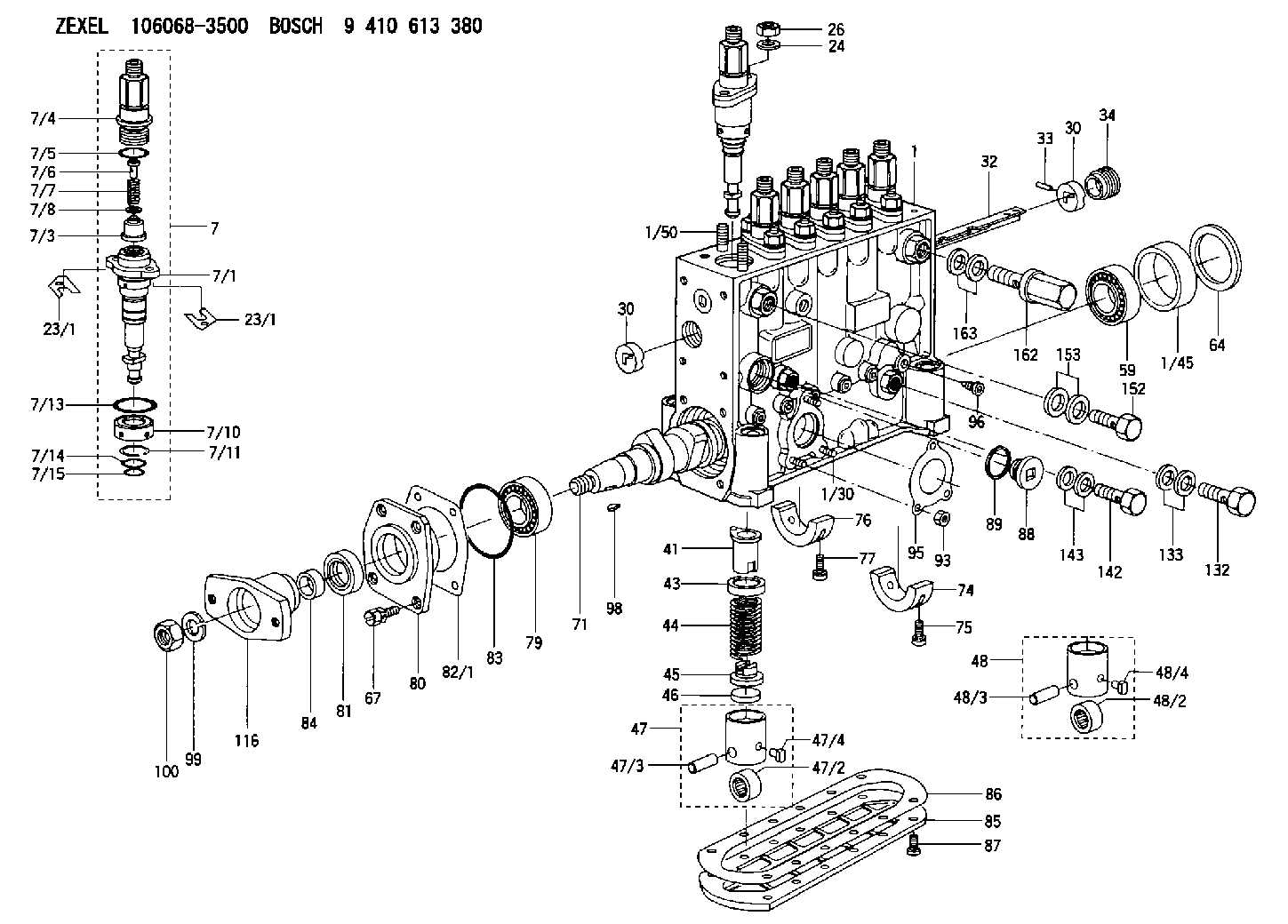
| 1. | [1] | 134070-0220 | PUMP HOUSING |
| 1/30. | [3] | 029040-6020 | STUD |
| 1/45. | [1] | 134311-0000 | SPACER RING |
| 1/50. | [12] | 134138-0100 | STUD |
| 7. | [6] | 134147-9420 | PLUNGER-AND-BARREL ASSY |
| 7/1. | [1] | 134173-4020 | PLUNGER-AND-BARREL ASSY |
| 7/3. | [1] | 134160-0120 | DELIVERY-VALVE ASSEMBLY |
| 7/4. | [1] | 134171-0120 | FITTING |
| 7/5. | [1] | 016500-1850 | O-RING |
| 7/6. | [1] | 134117-1700 | FILLER PIECE |
| 7/7. | [1] | 134112-2200 | COILED SPRING |
| 7/8. | [1] | 134115-0300 | GASKET |
| 7/10. | [1] | 134135-0300 | CAPSULE |
| 7/11. | [1] | 029602-0010 | LOCKING WASHER |
| 7/13. | [1] | 139727-0300 | O-RING |
| 7/14. | [1] | 139715-0300 | O-RING |
| 7/15. | [1] | 139715-0300 | O-RING |
| 23/1. | [0] | 139400-0900 | SHIM T0.500 |
| 23/1. | [0] | 139400-1000 | SHIM T0.525 |
| 23/1. | [0] | 139400-1100 | SHIM T0.550 |
| 23/1. | [0] | 139400-1100 | SHIM T0.550 |
| 23/1. | [0] | 139400-1200 | SHIM T0.575 |
| 23/1. | [0] | 139400-1300 | SHIM T0.600 |
| 23/1. | [0] | 139400-1400 | SHIM T0.625 |
| 23/1. | [0] | 139400-1500 | SHIM T0.650 |
| 23/1. | [0] | 139400-1600 | SHIM T0.675 |
| 23/1. | [0] | 139400-1700 | SHIM T0.700 |
| 23/1. | [0] | 139400-1800 | SHIM T0.725 |
| 23/1. | [0] | 139400-1900 | SHIM T0.750 |
| 23/1. | [0] | 139400-2000 | SHIM T0.775 |
| 23/1. | [0] | 139400-2100 | SHIM T0.800 |
| 23/1. | [0] | 139400-2200 | SHIM T0.825 |
| 23/1. | [0] | 139400-2300 | SHIM T0.850 |
| 23/1. | [0] | 139400-2400 | SHIM T0.875 |
| 23/1. | [0] | 139400-2500 | SHIM T0.900 |
| 23/1. | [0] | 139400-2600 | SHIM T0.925 |
| 23/1. | [0] | 139400-2700 | SHIM T0.950 |
| 23/1. | [0] | 139400-2800 | SHIM T0.975 |
| 23/1. | [0] | 139400-2900 | SHIM T1.000 |
| 23/1. | [0] | 139400-3000 | SHIM T1.025 |
| 23/1. | [0] | 139400-3100 | SHIM T1.050 |
| 23/1. | [0] | 139400-3200 | SHIM T1.075 |
| 23/1. | [0] | 139400-3300 | SHIM T1.100 |
| 23/1. | [0] | 139400-3400 | SHIM T1.125 |
| 23/1. | [0] | 139400-3500 | SHIM T1.150 |
| 23/1. | [0] | 139400-3600 | SHIM T1.175 |
| 23/1. | [0] | 139400-3700 | SHIM T1.200 |
| 23/1. | [0] | 139400-3800 | SHIM T1.225 |
| 23/1. | [0] | 139400-3900 | SHIM T1.250 |
| 23/1. | [0] | 139400-4000 | SHIM T1.275 |
| 23/1. | [0] | 139400-4100 | SHIM T1.300 |
| 23/1. | [0] | 139400-4200 | SHIM T1.325 |
| 23/1. | [0] | 139400-4300 | SHIM T1.350 |
| 23/1. | [0] | 139400-4400 | SHIM T1.375 |
| 23/1. | [0] | 139400-4500 | SHIM T1.400 |
| 23/1. | [0] | 139400-4600 | SHIM T1.425 |
| 23/1. | [0] | 139400-4700 | SHIM T1.450 |
| 23/1. | [0] | 139400-4800 | SHIM T1.475 |
| 23/1. | [0] | 139400-4900 | SHIM T1.500 |
| 23/1. | [0] | 139400-5000 | SHIM T1.525 |
| 23/1. | [0] | 139400-5100 | SHIM T1.550 |
| 23/1. | [0] | 139400-5200 | SHIM T1.575 |
| 23/1. | [0] | 139400-5300 | SHIM T1.600 |
| 23/1. | [0] | 139400-5400 | SHIM T1.625 |
| 23/1. | [0] | 139400-5500 | SHIM T1.650 |
| 23/1. | [0] | 139400-5600 | SHIM T1.675 |
| 23/1. | [0] | 139400-5700 | SHIM T1.700 |
| 23/1. | [0] | 139400-5800 | SHIM T1.725 |
| 23/1. | [0] | 139400-5900 | SHIM T1.750 |
| 23/1. | [0] | 139400-6000 | SHIM T1.775 |
| 23/1. | [0] | 139400-6100 | SHIM T1.800 |
| 23/1. | [0] | 139400-6200 | SHIM T1.825 |
| 23/1. | [0] | 139400-6300 | SHIM T1.850 |
| 23/1. | [0] | 139400-6400 | SHIM T1.875 |
| 23/1. | [0] | 139400-6500 | SHIM T1.900 |
| 23/1. | [0] | 139400-6600 | SHIM T1.925 |
| 23/1. | [0] | 139400-6700 | SHIM T1.950 |
| 23/1. | [0] | 139400-6800 | SHIM T1.975 |
| 24. | [12] | 134132-0300 | PLAIN WASHER D20&11T2.5 |
| 26. | [12] | 139210-0200 | UNION NUT |
| 30. | [2] | 134001-0000 | BUSHING |
| 30. | [2] | 134001-0000 | BUSHING |
| 32. | [1] | 134256-4500 | CONTROL RACK |
| 33. | [1] | 024030-2030 | BEARING PIN |
| 34. | [1] | 134222-0000 | BUSHING |
| 41. | [6] | 134241-0620 | CONTROL SLEEVE |
| 43. | [6] | 134216-0000 | SLOTTED WASHER |
| 44. | [6] | 134215-0800 | COMPRESSION SPRING |
| 45. | [6] | 134217-0700 | SLOTTED WASHER |
| 46. | [6] | 134563-2700 | SPRING SEAT |
| 47. | [4] | 134200-0820 | TAPPET |
| 47/2. | [1] | 134204-0200 | ROLLER |
| 47/3. | [1] | 134203-0000 | BEARING PIN |
| 47/4. | [1] | 131206-0500 | SLIDER |
| 48. | [2] | 134200-0720 | TAPPET |
| 48/2. | [1] | 134204-0200 | ROLLER |
| 48/3. | [1] | 134203-0000 | BEARING PIN |
| 48/4. | [1] | 131206-0500 | SLIDER |
| 59. | [1] | 016650-2230 | BEARING PLATE |
| 64. | [1] | 134303-0500 | SHIM D59.8&43T1.6 |
| 67. | [4] | 139006-4200 | BLEEDER SCREW |
| 71. | [1] | 134340-0200 | CAMSHAFT |
| 74. | [1] | 134306-1000 | BEARING SHELL |
| 75. | [2] | 020106-2040 | BLEEDER SCREW M6P1L20 |
| 76. | [2] | 134306-1100 | BEARING SHELL |
| 77. | [4] | 020106-2040 | BLEEDER SCREW M6P1L20 |
| 79. | [1] | 035302-0600 | BEARING PLATE |
| 80. | [1] | 134316-3300 | COVER |
| 81. | [1] | 139634-0200 | PACKING RING |
| 82/1. | [0] | 134314-0700 | SHIM T0.1 |
| 82/1. | [0] | 134314-0800 | SHIM T0.12 |
| 82/1. | [0] | 134314-0900 | SHIM T0.14 |
| 82/1. | [0] | 134314-1000 | SHIM T0.16 |
| 82/1. | [0] | 134314-1100 | SHIM T0.18 |
| 82/1. | [0] | 134314-1200 | SHIM T0.3 |
| 82/1. | [0] | 134314-1300 | SHIM T0.5 |
| 83. | [1] | 139766-0000 | O-RING |
| 84. | [1] | 134563-2500 | SLIDING PIECE |
| 85. | [1] | 134043-0800 | COVER |
| 86. | [1] | 134042-1400 | GASKET |
| 87. | [12] | 012206-1640 | FLAT-HEAD SCREW M6P1L16 |
| 88. | [1] | 134045-0100 | CAPSULE |
| 89. | [1] | 026524-2940 | GASKET D28.9&24.3T2 |
| 93. | [3] | 139206-0400 | UNION NUT |
| 95. | [1] | 131041-0800 | GASKET |
| 96. | [6] | 134047-0000 | CAPSULE |
| 98. | [1] | 025806-2210 | WOODRUFF KEY |
| 99. | [1] | 014112-0440 | LOCKING WASHER |
| 100. | [1] | 023012-0040 | UNION NUT M20P1.5H16 |
| 116. | [1] | 156638-4800 | COUPLING PLATE |
| 132. | [1] | 029731-4680 | EYE BOLT |
| 133. | [2] | 029341-4130 | GASKET D20&13.8T2* |
| 142. | [1] | 029731-0120 | EYE BOLT |
| 143. | [2] | 029341-0110 | GASKET |
| 152. | [1] | 029731-4680 | EYE BOLT |
| 153. | [2] | 029341-4130 | GASKET D20&13.8T2* |
| 162. | [1] | 131425-1620 | OVER FLOW VALVE |
| 163. | [2] | 029341-4130 | GASKET D20&13.8T2* |
Include in #1:
106685-4231
as FUEL INJECTION PUMP
Cross reference number
Zexel num
Bosch num
Firm num
Name
Information:
37. Remove dowels (72) and flyweights (73) from the carrier assembly.38. Remove dowel (71) from the governor shaft, and remove the governor shaft from the carrier assembly. 39. Remove races (74) and (76) and bearing (75) from the camshaft in the fuel injection pump housing.Assemble Governor
1. Put the fuel injection pump housing in position on tool (A). Install race (76) bearing (75) and race (74) on the end of the camshaft in the fuel injection pump housing. 2. Put flyweights (73) in position on carrier assembly (70), and install dowels (72) to hold the flyweights in place. The flyweights must move freely on the dowels and have 0.010 to 0.230 mm (.0004 to .0090 in.) end play. 3. Install governor shaft (77) on carrier assembly (70). 4. Install dowel (71) in governor shaft (77) and slide carrier assembly (70) down on the governor shaft until dowel (71) fits into the slot in the carrier assembly.5. Install carrier assembly (70) on the end of the camshaft. 6. Install race (68), bearing (69), race (68) and ring (67) on riser (65). 7. Install riser (65) and spring (66), if equipped, on the governor shaft. 8. Install spool (62) and ring (63) on seat (61) and use tool (B) to install ring (64) to hold them in position.9. Install seat (61) on spring (60). Install spring (60) on shield (59). 10. Install dashpot assembly (58) on the governor shaft. 11. Install ring (57) in the groove on the governor shaft. Install sleeve (78), spring (55), the sleeve and bearing (56) on the governor shaft. 12. Use tool (C) to hold spring (55) under compression, and install the ring in the groove on the governor shaft. 13. Put lever (52) in position on governor servo (53), and install pin (51) to hold the lever in place. Use a hammer and chisel to move the metal (stake) four places 90° apart on the outside surface on both legs of the governor servo to hold pin (51) in place.14. Install O-ring seal (54) on sleeve (48). Install piston (50) and sleeve (48) in the governor servo as shown.15. Install valve (49) in the governor servo as shown. 16. Install lockring (42) in the groove near the center of valve (43). Put sleeve (44), spring (broken link spring) (45) and seat (46) in position on valve (43), and install lockring (47) to hold them in place. 17. Put governor servo (41) in position on the fuel injection pump housing with piston (50) engaged over the rack. Make sure the lever is engaged in the (slot) groove of riser (65). 18. If dowel (82) was removed, install it in block (83) 31 0.5 mm (1.22 .02 in.) above the outside surface of the block.19. Install bolt (40) in block (83) and spring (38) on bolt (40).20. Install stop screw (80) and the locknut on collar (39). Install power setting screw (81) and the locknut on the collar.21. Install collar (39) on bolt (40). Make
1. Put the fuel injection pump housing in position on tool (A). Install race (76) bearing (75) and race (74) on the end of the camshaft in the fuel injection pump housing. 2. Put flyweights (73) in position on carrier assembly (70), and install dowels (72) to hold the flyweights in place. The flyweights must move freely on the dowels and have 0.010 to 0.230 mm (.0004 to .0090 in.) end play. 3. Install governor shaft (77) on carrier assembly (70). 4. Install dowel (71) in governor shaft (77) and slide carrier assembly (70) down on the governor shaft until dowel (71) fits into the slot in the carrier assembly.5. Install carrier assembly (70) on the end of the camshaft. 6. Install race (68), bearing (69), race (68) and ring (67) on riser (65). 7. Install riser (65) and spring (66), if equipped, on the governor shaft. 8. Install spool (62) and ring (63) on seat (61) and use tool (B) to install ring (64) to hold them in position.9. Install seat (61) on spring (60). Install spring (60) on shield (59). 10. Install dashpot assembly (58) on the governor shaft. 11. Install ring (57) in the groove on the governor shaft. Install sleeve (78), spring (55), the sleeve and bearing (56) on the governor shaft. 12. Use tool (C) to hold spring (55) under compression, and install the ring in the groove on the governor shaft. 13. Put lever (52) in position on governor servo (53), and install pin (51) to hold the lever in place. Use a hammer and chisel to move the metal (stake) four places 90° apart on the outside surface on both legs of the governor servo to hold pin (51) in place.14. Install O-ring seal (54) on sleeve (48). Install piston (50) and sleeve (48) in the governor servo as shown.15. Install valve (49) in the governor servo as shown. 16. Install lockring (42) in the groove near the center of valve (43). Put sleeve (44), spring (broken link spring) (45) and seat (46) in position on valve (43), and install lockring (47) to hold them in place. 17. Put governor servo (41) in position on the fuel injection pump housing with piston (50) engaged over the rack. Make sure the lever is engaged in the (slot) groove of riser (65). 18. If dowel (82) was removed, install it in block (83) 31 0.5 mm (1.22 .02 in.) above the outside surface of the block.19. Install bolt (40) in block (83) and spring (38) on bolt (40).20. Install stop screw (80) and the locknut on collar (39). Install power setting screw (81) and the locknut on the collar.21. Install collar (39) on bolt (40). Make