Information fuel-injection pump
BOSCH
9 410 613 527
9410613527
ZEXEL
106068-3492
1060683492
Rating:
Scheme ###:
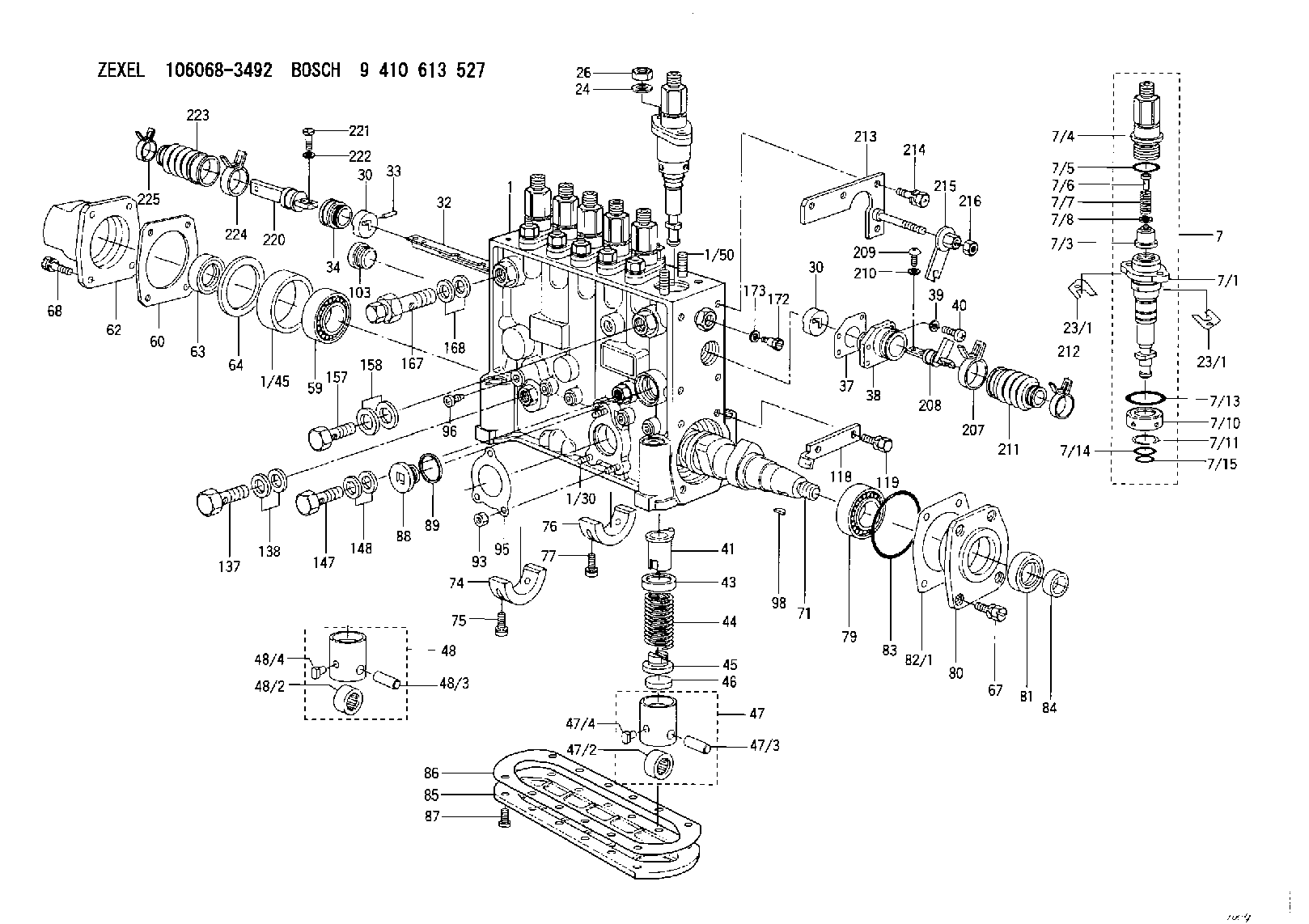
| 1. | [1] | 134070-4021 | PUMP HOUSING |
| 1/30. | [3] | 029040-6020 | STUD |
| 1/45. | [1] | 134311-0000 | SPACER RING |
| 1/50. | [12] | 134138-0100 | STUD |
| 7. | [6] | 134147-6220 | PLUNGER-AND-BARREL ASSY |
| 7/1. | [6] | 134173-0620 | PLUNGER-AND-BARREL ASSY S6 |
| 7/3. | [6] | 134160-1420 | DELIVERY-VALVE ASSEMBLY 14P |
| 7/4. | [6] | 134171-0320 | FITTING |
| 7/5. | [6] | 016500-1850 | O-RING |
| 7/6. | [6] | 134117-1700 | FILLER PIECE |
| 7/7. | [6] | 134112-2200 | COILED SPRING |
| 7/8. | [6] | 134115-0300 | GASKET |
| 7/10. | [6] | 134135-0300 | CAPSULE |
| 7/11. | [6] | 029602-0010 | LOCKING WASHER |
| 7/13. | [6] | 139727-0300 | O-RING |
| 7/14. | [6] | 139715-0200 | O-RING |
| 7/15. | [6] | 139715-0200 | O-RING |
| 23/1. | [0] | 139400-0900 | SHIM T0.500 |
| 23/1. | [0] | 139400-0900 | SHIM T0.500 |
| 23/1. | [0] | 139400-1000 | SHIM T0.525 |
| 23/1. | [0] | 139400-1100 | SHIM T0.550 |
| 23/1. | [0] | 139400-1200 | SHIM T0.575 |
| 23/1. | [0] | 139400-1300 | SHIM T0.600 |
| 23/1. | [0] | 139400-1400 | SHIM T0.625 |
| 23/1. | [0] | 139400-1500 | SHIM T0.650 |
| 23/1. | [0] | 139400-1600 | SHIM T0.675 |
| 23/1. | [0] | 139400-1700 | SHIM T0.700 |
| 23/1. | [0] | 139400-1800 | SHIM T0.725 |
| 23/1. | [0] | 139400-1900 | SHIM T0.750 |
| 23/1. | [0] | 139400-2000 | SHIM T0.775 |
| 23/1. | [0] | 139400-2100 | SHIM T0.800 |
| 23/1. | [0] | 139400-2200 | SHIM T0.825 |
| 23/1. | [0] | 139400-2300 | SHIM T0.850 |
| 23/1. | [0] | 139400-2400 | SHIM T0.875 |
| 23/1. | [0] | 139400-2500 | SHIM T0.900 |
| 23/1. | [0] | 139400-2600 | SHIM T0.925 |
| 23/1. | [0] | 139400-2700 | SHIM T0.950 |
| 23/1. | [0] | 139400-2800 | SHIM T0.975 |
| 23/1. | [0] | 139400-2900 | SHIM T1.000 |
| 23/1. | [0] | 139400-3000 | SHIM T1.025 |
| 23/1. | [0] | 139400-3100 | SHIM T1.050 |
| 23/1. | [0] | 139400-3200 | SHIM T1.075 |
| 23/1. | [0] | 139400-3300 | SHIM T1.100 |
| 23/1. | [0] | 139400-3400 | SHIM T1.125 |
| 23/1. | [0] | 139400-3500 | SHIM T1.150 |
| 23/1. | [0] | 139400-3600 | SHIM T1.175 |
| 23/1. | [0] | 139400-3700 | SHIM T1.200 |
| 23/1. | [0] | 139400-3800 | SHIM T1.225 |
| 23/1. | [0] | 139400-3900 | SHIM T1.250 |
| 23/1. | [0] | 139400-4000 | SHIM T1.275 |
| 23/1. | [0] | 139400-4100 | SHIM T1.300 |
| 23/1. | [0] | 139400-4200 | SHIM T1.325 |
| 23/1. | [0] | 139400-4300 | SHIM T1.350 |
| 23/1. | [0] | 139400-4400 | SHIM T1.375 |
| 23/1. | [0] | 139400-4500 | SHIM T1.400 |
| 23/1. | [0] | 139400-4600 | SHIM T1.425 |
| 23/1. | [0] | 139400-4700 | SHIM T1.450 |
| 23/1. | [0] | 139400-4800 | SHIM T1.475 |
| 23/1. | [0] | 139400-4900 | SHIM T1.500 |
| 23/1. | [0] | 139400-5000 | SHIM T1.525 |
| 23/1. | [0] | 139400-5100 | SHIM T1.550 |
| 23/1. | [0] | 139400-5200 | SHIM T1.575 |
| 23/1. | [0] | 139400-5300 | SHIM T1.600 |
| 23/1. | [0] | 139400-5400 | SHIM T1.625 |
| 23/1. | [0] | 139400-5500 | SHIM T1.650 |
| 23/1. | [0] | 139400-5600 | SHIM T1.675 |
| 23/1. | [0] | 139400-5700 | SHIM T1.700 |
| 23/1. | [0] | 139400-5800 | SHIM T1.725 |
| 23/1. | [0] | 139400-5900 | SHIM T1.750 |
| 23/1. | [0] | 139400-6000 | SHIM T1.775 |
| 23/1. | [0] | 139400-6100 | SHIM T1.800 |
| 23/1. | [0] | 139400-6200 | SHIM T1.825 |
| 23/1. | [0] | 139400-6300 | SHIM T1.850 |
| 23/1. | [0] | 139400-6400 | SHIM T1.875 |
| 23/1. | [0] | 139400-6500 | SHIM T1.900 |
| 23/1. | [0] | 139400-6600 | SHIM T1.925 |
| 23/1. | [0] | 139400-6700 | SHIM T1.950 |
| 23/1. | [0] | 139400-6800 | SHIM T1.975 |
| 24. | [12] | 134132-0300 | PLAIN WASHER |
| 26. | [12] | 139210-0200 | UNION NUT |
| 30. | [2] | 134001-0200 | BUSHING |
| 30. | [2] | 134001-0200 | BUSHING |
| 32. | [1] | 134256-5300 | CONTROL RACK |
| 33. | [1] | 024030-2030 | BEARING PIN |
| 34. | [1] | 134222-1800 | BUSHING |
| 37. | [1] | 134510-6800 | GASKET |
| 38. | [1] | 134222-1300 | ADAPTOR |
| 39. | [4] | 014110-4440 | LOCKING WASHER D7.6&4.1T1 |
| 40. | [4] | 012154-1440 | FLAT-HEAD SCREW |
| 41. | [6] | 134241-0620 | CONTROL SLEEVE |
| 43. | [6] | 134216-0000 | SLOTTED WASHER |
| 44. | [6] | 134215-0800 | COMPRESSION SPRING |
| 45. | [6] | 134217-0700 | SLOTTED WASHER |
| 46. | [6] | 134563-2700 | SPRING SEAT |
| 47. | [4] | 134200-0820 | TAPPET |
| 47/2. | [4] | 134204-0200 | ROLLER |
| 47/3. | [4] | 134203-0000 | BEARING PIN |
| 47/4. | [4] | 131206-0500 | SLIDER |
| 48. | [2] | 134200-0720 | TAPPET |
| 48/2. | [2] | 134204-0200 | ROLLER |
| 48/3. | [2] | 134203-0000 | BEARING PIN |
| 48/4. | [2] | 131206-0500 | SLIDER |
| 59. | [1] | 016650-2230 | BEARING PLATE 4T-32205(NSK) |
| 60. | [1] | 134312-0000 | GASKET |
| 62. | [1] | 134316-0320 | COVER |
| 63. | [1] | 029621-7020 | PACKING RING |
| 64. | [1] | 134303-0500 | SHIM |
| 67. | [4] | 139006-4200 | BLEEDER SCREW |
| 68. | [4] | 139006-4100 | BLEEDER SCREW |
| 71. | [1] | 134340-0700 | CAMSHAFT |
| 74. | [1] | 134306-1000 | BEARING SHELL |
| 75. | [2] | 020106-2040 | BLEEDER SCREW |
| 76. | [2] | 134306-1100 | BEARING SHELL |
| 77. | [4] | 020106-2040 | BLEEDER SCREW |
| 79. | [1] | 035302-0600 | BEARING PLATE |
| 80. | [1] | 134316-3300 | COVER |
| 81. | [1] | 139634-0200 | PACKING RING |
| 82/1. | [0] | 134314-0700 | SHIM T0.1 |
| 82/1. | [0] | 134314-0800 | SHIM T0.12 |
| 82/1. | [0] | 134314-0900 | SHIM T0.14 |
| 82/1. | [0] | 134314-1000 | SHIM T0.16 |
| 82/1. | [0] | 134314-1100 | SHIM T0.18 |
| 82/1. | [0] | 134314-1200 | SHIM T0.3 |
| 82/1. | [0] | 134314-1300 | SHIM T0.5 |
| 83. | [1] | 139766-0200 | O-RING |
| 84. | [1] | 134563-2500 | SLIDING PIECE |
| 85. | [1] | 134043-0800 | COVER |
| 86. | [1] | 134042-1400 | GASKET |
| 87. | [12] | 012206-1640 | FLAT-HEAD SCREW |
| 88. | [1] | 134045-0100 | CAPSULE |
| 89. | [1] | 026524-2940 | GASKET |
| 93. | [3] | 139206-0400 | UNION NUT |
| 95. | [1] | 131041-0800 | GASKET |
| 96. | [6] | 134047-0000 | CAPSULE |
| 98. | [1] | 025806-2210 | WOODRUFF KEY |
| 103. | [1] | 134026-0000 | CAPSULE |
| 118. | [1] | 134496-3500 | POINTER |
| 119. | [2] | 020006-1240 | BLEEDER SCREW |
| 137. | [1] | 029731-4680 | EYE BOLT |
| 138. | [2] | 029341-4130 | GASKET |
| 147. | [1] | 134430-0200 | EYE BOLT |
| 148. | [2] | 029341-0110 | GASKET |
| 157. | [1] | 029731-4570 | EYE BOLT |
| 158. | [2] | 029341-4130 | GASKET |
| 167. | [1] | 131424-3420 | OVER FLOW VALVE |
| 168. | [2] | 029341-4130 | GASKET |
| 172. | [1] | 131420-0400 | BLEEDER SCREW |
| 173. | [1] | 026506-1040 | GASKET |
| 207. | [1] | 134563-4300 | CLAMPING BAND |
| 208. | [1] | 134563-8620 | CONNECTOR |
| 209. | [2] | 010635-1240 | FLAT-HEAD SCREW |
| 210. | [2] | 014110-5440 | LOCKING WASHER |
| 211. | [1] | 134563-4200 | COVER |
| 212. | [1] | 134563-3700 | CLAMPING BAND |
| 213. | [1] | 134510-7520 | BRACKET |
| 214. | [3] | 020106-2040 | BLEEDER SCREW |
| 215. | [1] | 134513-0300 | PLATE |
| 216. | [1] | 154011-2100 | UNION NUT |
| 220. | [1] | 134563-9000 | CONNECTOR |
| 221. | [2] | 010635-1240 | FLAT-HEAD SCREW |
| 222. | [2] | 014110-5440 | LOCKING WASHER |
| 223. | [1] | 134563-4200 | COVER |
| 224. | [1] | 134563-4300 | CLAMPING BAND |
| 225. | [1] | 134563-3700 | CLAMPING BAND |
Include in #1:
106684-4362
as FUEL INJECTION PUMP
Cross reference number
Zexel num
Bosch num
Firm num
Name
Information:
1. Remove nuts (2) and remove cover (1) from the timing gear cover. Remove the gasket from cover (1). 2. Remove bolts and washers (3). Remove cover (4). 3. Remove O-ring seals (5) from cover (4). 4. Remove bolts (6). Remove ring (7) and the gear. 5. Remove fuel injection lines (9). Put caps and plugs on the openings of the pump and lines to prevent contamination from entering the fuel system.6. Remove tube assembly (8). Remove tube assemblies (11) and fuel manifold (10). Remove fuel transfer pump (12). 7. The weight of the fuel injection pump housing and governor is 57 kg (125 lb.). Attach a hoist to the fuel injection pump housing, and remove two bolts (16), and two bolts (17).8. Remove two nuts (13) and bolt (14). Remove fuel injection pump housing and governor (15). 9. Remove O-ring seals (18) from fuel injection pump housing (15). The following steps are for the installation of the fuel injection pump housing and governor.10. Attach a hoist to the fuel injection pump housing and governor (15). Be sure that the three O-ring seals are in position on the fuel infection pump housing. Install the fuel injection pump housing and governor on the timing gear housing.11. Install fuel transfer pump (12) and fuel manifold (10). Install tube assemblies (8) and (11).12. Install fuel injection lines (9). 13. Put gear (19) in position in the front timing gear cover. 14. Install two 3/8"-16 NC × 152.4 mm (6 in.) guide bolts (20) in gear (19) as shown. 15. Install ring (7). Install two bolts (6) finger tight. Remove guide pins (20) and install the remaining bolts (6). Tighten bolts (6) to a torque of 3 N m (27 lb. in.).16. Put the O-ring seals on cover (4). Lubricate the seals with clean engine oil. Put cover (4) in postion on ring (7) and install bolts and washers (3). 17. Put the No. 1 piston at top center on the compression stroke. Make reference to the topic, Finding Top Center Compression Position For No. 1 Piston, in Testing And Adjusting. Remove the timing bolt from the flywheel, and use tool (A) to rotate the crankshaft clockwise (opposite the direction of engine rotation) 45°. 18. Remove the plug from the fuel injection pump housing. Install tool (B) in the fuel injection pump housing as shown. Slowly rotate the crankshaft counterclockwise (direction of engine rotation) until the timing pin goes into the slot in the fuel injection pump camshaft.
Too much pressure on the timing pin can damage the fuel injection pump or the timing pin.
19. Put the timing bolt in the timing hole in the flywheel housing. Rotate the crankshaft counterclockwise (as viewed from the flywheel end of the engine) until the fuel pump camshaft is tight against tool (B). This removes gear clearance from the drive train. If the bolt can be installed in the timing hole in the flywheel, the timing of the fuel injection pump is correct.20. If the