Information fuel-injection pump
BOSCH
9 410 613 306
9410613306
ZEXEL
106067-6360
1060676360
Rating:
Scheme ###:
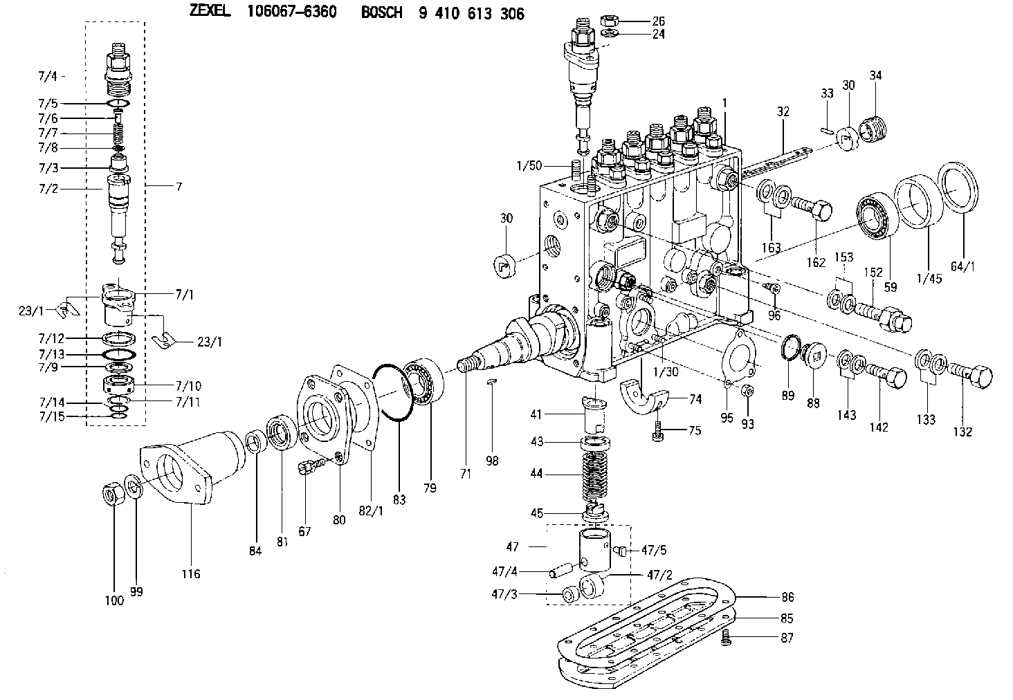
| 1. | [1] | 134063-5720 | PUMP HOUSING |
| 1/30. | [3] | 029040-6020 | STUD |
| 1/45. | [1] | 134311-0000 | SPACER RING |
| 1/50. | [12] | 134138-0000 | STUD |
| 7. | [6] | 134150-7220 | PLUNGER-AND-BARREL ASSY |
| 7/1. | [1] | 134131-1020 | FLANGE BUSHING |
| 7/2. | [1] | 134153-4620 | PLUNGER-AND-BARREL ASSY |
| 7/3. | [1] | 134110-8920 | DELIVERY-VALVE ASSEMBLY |
| 7/4. | [1] | 134116-4720 | FITTING |
| 7/5. | [1] | 139722-0200 | O-RING |
| 7/6. | [1] | 134117-0500 | FILLER PIECE |
| 7/7. | [1] | 134112-2000 | COILED SPRING |
| 7/8. | [1] | 134115-0100 | GASKET |
| 7/9. | [1] | 029302-0140 | PLAIN WASHER |
| 7/10. | [1] | 134135-0200 | CAPSULE |
| 7/11. | [1] | 029602-0010 | LOCKING WASHER |
| 7/12. | [1] | 134137-0100 | SPACER RING |
| 7/13. | [1] | 139729-0000 | O-RING |
| 7/14. | [1] | 139715-0200 | O-RING |
| 7/15. | [1] | 139715-0200 | O-RING |
| 23/1. | [0] | 139400-0900 | SHIM T0.500 |
| 23/1. | [0] | 139400-1000 | SHIM T0.525 |
| 23/1. | [0] | 139400-1100 | SHIM T0.550 |
| 23/1. | [0] | 139400-1200 | SHIM T0.575 |
| 23/1. | [0] | 139400-1300 | SHIM T0.600 |
| 23/1. | [0] | 139400-1400 | SHIM T0.625 |
| 23/1. | [0] | 139400-1500 | SHIM T0.650 |
| 23/1. | [0] | 139400-1600 | SHIM T0.675 |
| 23/1. | [0] | 139400-1700 | SHIM T0.700 |
| 23/1. | [0] | 139400-1800 | SHIM T0.725 |
| 23/1. | [0] | 139400-1900 | SHIM T0.750 |
| 23/1. | [0] | 139400-2000 | SHIM T0.775 |
| 23/1. | [0] | 139400-2100 | SHIM T0.800 |
| 23/1. | [0] | 139400-2200 | SHIM T0.825 |
| 23/1. | [0] | 139400-2300 | SHIM T0.850 |
| 23/1. | [0] | 139400-2400 | SHIM T0.875 |
| 23/1. | [0] | 139400-2500 | SHIM T0.900 |
| 23/1. | [0] | 139400-2600 | SHIM T0.925 |
| 23/1. | [0] | 139400-2700 | SHIM T0.950 |
| 23/1. | [0] | 139400-2800 | SHIM T0.975 |
| 23/1. | [0] | 139400-2900 | SHIM T1.000 |
| 23/1. | [0] | 139400-3000 | SHIM T1.025 |
| 23/1. | [0] | 139400-3100 | SHIM T1.050 |
| 23/1. | [0] | 139400-3200 | SHIM T1.075 |
| 23/1. | [0] | 139400-3300 | SHIM T1.100 |
| 23/1. | [0] | 139400-3400 | SHIM T1.125 |
| 23/1. | [0] | 139400-3500 | SHIM T1.150 |
| 23/1. | [0] | 139400-3600 | SHIM T1.175 |
| 23/1. | [0] | 139400-3700 | SHIM T1.200 |
| 23/1. | [0] | 139400-3800 | SHIM T1.225 |
| 23/1. | [0] | 139400-3900 | SHIM T1.250 |
| 23/1. | [0] | 139400-4000 | SHIM T1.275 |
| 23/1. | [0] | 139400-4100 | SHIM T1.300 |
| 23/1. | [0] | 139400-4200 | SHIM T1.325 |
| 23/1. | [0] | 139400-4300 | SHIM T1.350 |
| 23/1. | [0] | 139400-4400 | SHIM T1.375 |
| 23/1. | [0] | 139400-4500 | SHIM T1.400 |
| 23/1. | [0] | 139400-4600 | SHIM T1.425 |
| 23/1. | [0] | 139400-4700 | SHIM T1.450 |
| 23/1. | [0] | 139400-4800 | SHIM T1.475 |
| 23/1. | [0] | 139400-4900 | SHIM T1.500 |
| 23/1. | [0] | 139400-5000 | SHIM T1.525 |
| 23/1. | [0] | 139400-5100 | SHIM T1.550 |
| 23/1. | [0] | 139400-5200 | SHIM T1.575 |
| 23/1. | [0] | 139400-5300 | SHIM T1.600 |
| 23/1. | [0] | 139400-5400 | SHIM T1.625 |
| 23/1. | [0] | 139400-5500 | SHIM T1.650 |
| 23/1. | [0] | 139400-5600 | SHIM T1.675 |
| 23/1. | [0] | 139400-5700 | SHIM T1.700 |
| 23/1. | [0] | 139400-5700 | SHIM T1.700 |
| 23/1. | [0] | 139400-5800 | SHIM T1.725 |
| 23/1. | [0] | 139400-5900 | SHIM T1.750 |
| 23/1. | [0] | 139400-6000 | SHIM T1.775 |
| 23/1. | [0] | 139400-6100 | SHIM T1.800 |
| 23/1. | [0] | 139400-6200 | SHIM T1.825 |
| 23/1. | [0] | 139400-6300 | SHIM T1.850 |
| 23/1. | [0] | 139400-6400 | SHIM T1.875 |
| 23/1. | [0] | 139400-6500 | SHIM T1.900 |
| 23/1. | [0] | 139400-6600 | SHIM T1.925 |
| 23/1. | [0] | 139400-6700 | SHIM T1.950 |
| 23/1. | [0] | 139400-6800 | SHIM T1.975 |
| 24. | [12] | 134132-0300 | PLAIN WASHER D20&11T2.5 |
| 26. | [12] | 013021-0040 | UNION NUT M10P1.5H8 |
| 30. | [2] | 134001-0000 | BUSHING |
| 30. | [2] | 134001-0000 | BUSHING |
| 32. | [1] | 134256-0000 | CONTROL RACK |
| 33. | [1] | 024030-2030 | BEARING PIN |
| 34. | [1] | 134222-0000 | BUSHING |
| 41. | [6] | 134241-0320 | CONTROL SLEEVE |
| 43. | [6] | 134216-0000 | SLOTTED WASHER |
| 44. | [6] | 134215-0700 | COILED SPRING |
| 45. | [6] | 134217-0500 | SLOTTED WASHER |
| 47. | [6] | 134200-0420 | TAPPET |
| 47/2. | [1] | 134204-0100 | ROLLER |
| 47/3. | [1] | 134205-0000 | BUSHING |
| 47/4. | [1] | 134203-0000 | BEARING PIN |
| 47/5. | [1] | 131206-0500 | SLIDER |
| 59. | [1] | 016650-2230 | BEARING PLATE |
| 64/1. | [0] | 134303-0000 | SHIM D59.8&43T1.2 |
| 64/1. | [0] | 134303-0100 | SHIM D59.8&43T1.5 |
| 64/1. | [0] | 134303-0200 | SHIM D59.8&43T1.8 |
| 64/1. | [0] | 134303-0300 | SHIM D59.8&43T2.0 |
| 64/1. | [0] | 134303-0400 | SHIM D59.8&43T0.6 |
| 67. | [4] | 029010-6810 | BLEEDER SCREW |
| 71. | [1] | 134371-5700 | CAMSHAFT |
| 74. | [1] | 134306-0600 | BEARING SHELL |
| 75. | [2] | 020106-2040 | BLEEDER SCREW M6P1L20 |
| 79. | [1] | 016650-2230 | BEARING PLATE |
| 80. | [1] | 134316-1700 | COVER |
| 81. | [1] | 139629-0000 | PACKING RING |
| 82/1. | [0] | 134314-0000 | SHIM T0.1 |
| 82/1. | [0] | 134314-0100 | SHIM T0.12 |
| 82/1. | [0] | 134314-0200 | SHIM T0.14 |
| 82/1. | [0] | 134314-0300 | SHIM T0.16 |
| 82/1. | [0] | 134314-0400 | SHIM T0.18 |
| 82/1. | [0] | 134314-0500 | SHIM T0.3 |
| 82/1. | [0] | 134314-0600 | SHIM T0.5 |
| 83. | [1] | 029635-5010 | O-RING |
| 84. | [1] | 134563-0900 | SLIDING PIECE |
| 85. | [1] | 134043-0800 | COVER |
| 86. | [1] | 134042-1400 | GASKET |
| 87. | [12] | 012206-1640 | FLAT-HEAD SCREW M6P1L16 |
| 88. | [1] | 134045-0100 | CAPSULE |
| 89. | [1] | 026524-2940 | GASKET D28.9&24.3T2 |
| 93. | [3] | 139206-0400 | UNION NUT |
| 95. | [1] | 131041-0800 | GASKET |
| 96. | [6] | 134047-0000 | CAPSULE |
| 98. | [1] | 025805-1910 | WOODRUFF KEY |
| 99. | [1] | 023641-8410 | LOCKING WASHER |
| 100. | [1] | 134325-0700 | UNION NUT |
| 116. | [1] | 156636-8900 | COUPLING PLATE |
| 132. | [1] | 029731-4080 | EYE BOLT |
| 133. | [2] | 029341-4130 | GASKET D20&13.8T2* |
| 142. | [1] | 029731-0120 | EYE BOLT |
| 143. | [2] | 029341-0110 | GASKET |
| 152. | [1] | 131425-2120 | OVER FLOW VALVE |
| 153. | [2] | 029341-4130 | GASKET D20&13.8T2* |
| 162. | [1] | 029731-4680 | EYE BOLT |
| 163. | [2] | 029341-4130 | GASKET D20&13.8T2* |
Cross reference number
Zexel num
Bosch num
Firm num
Name
Information:
Stopping the engine immediately after it has been working under load can result in overheating and accelerated wear of the engine components. Excessive temperatures in the turbocharger centerhousing will cause oil coking problems.
Prior to stopping an engine that is being operated at low loads, run the engine at low speed for 30 seconds before stopping. If the engine has been operating at high load, then it should be run at low speed for three to five minutes to reduce and stabilize internal engine coolant and oil temperatures before stopping. Avoiding hot engine shutdowns will maximize turbocharger shaft and bearing life. Make sure the Engine Stopping procedure is understood.Follow the engine stopping procedure outlined below to allow the engine to cool. Make sure the Engine Stopping procedure is understood.The engine may be shutdown in several ways. To manually stop the engine, refer to the following information and instructions. The engine is equipped with an Emergency Stop Push Button (ESPB) and an Engine Control Switch (ECS), which is OEM provided.Emergency Stop Procedure
Emergency stop controls are for EMERGENCY use ONLY. DO NOT use Emergency Stop Pushbutton (ESPB) for normal stopping procedure. Do NOT start the engine until the problem necessitating the emergency stop has been located and corrected.
The engine may be installed with an Emergency Stop Pushbutton. The Emergency Stop Pushbutton may be located on the front of the control panel. The Emergency Stop Pushbutton will cause immediate shutoff of fuel and/or air. Emergency shutoff controls (including any auxiliary Emergency Stop inputs) should only be used when an emergency exists, and not used to routinely stop the engine.* Emergency stops may be made through the Emergency Stop Pushbutton (ESPB). If the need for emergency engine shutdown occurs, Push the EMERGENCY STOP Pushbutton located on the control panel. This will activate the air and/or fuel shutoffs.* Reset the EMERGENCY STOP Pushbutton (pull out and rotate the button in the direction indicated on the button). Some EMERGENCY STOP Pushbuttons can be pulled out to reset, not requiring any rotation.Manual Fuel Shutoff
A manual shutdown shaft is provided to override the governor control of the engine. This shutdown will only move the fuel control linkage to the fuel OFF position to starve the engine of fuel. The engine will coast to a stop. Be sure to secure any external system components that have been operating to support the engine operation.Manual Stop Procedure
Follow the engine stopping procedure outlined below, to allow the engine to cool. Make sure the Engine Stopping procedure is clearly understood.1. Reduce engine speed to low idle.2. Disengage driven equipment or remove load from engine.3. Move governor control to increase engine speed to no more than half engine speed for two minutes.4. Reduce engine speed to low idle for five minutes to cool the engine and prevent oil coking problems in the turbocharger centerhousing.5. Depending on your control, stop the engine by turning the start switch to the OFF position or refer below to the governor controls that your engine may be equipped