Information fuel-injection pump
BOSCH
9 410 612 119
9410612119
ZEXEL
106066-5610
1060665610
NISSAN-DIESEL
1670196775
1670196775
Rating:
Scheme ###:
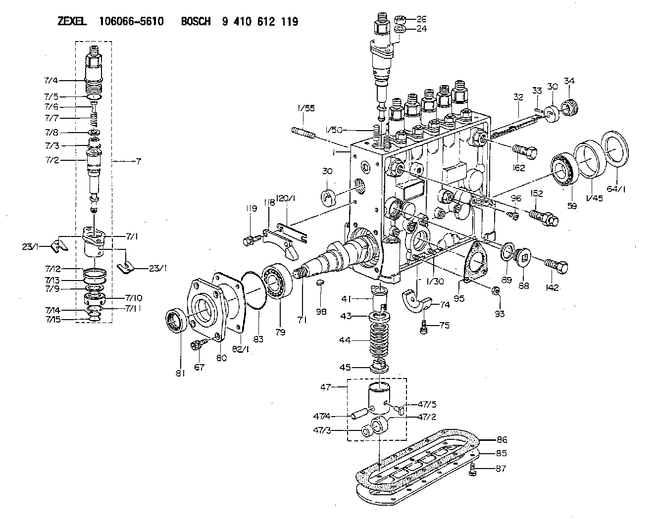
| 1. | [1] | 134051-1520 | PUMP HOUSING |
| 1/30. | [3] | 029040-6020 | STUD |
| 1/45. | [1] | 134311-0000 | SPACER RING |
| 1/50. | [12] | 134138-0000 | STUD |
| 1/55. | [2] | 139008-0700 | STUD |
| 7. | [6] | 134146-2820 | PLUNGER-AND-BARREL ASSY |
| 7/1. | [6] | 134131-1020 | FLANGE BUSHING |
| 7/2. | [6] | 134151-8520 | PLUNGER-AND-BARREL ASSY |
| 7/3. | [6] | 134110-8920 | DELIVERY-VALVE ASSEMBLY |
| 7/4. | [6] | 134116-0700 | FITTING |
| 7/5. | [6] | 139722-0100 | O-RING |
| 7/6. | [6] | 134117-0500 | FILLER PIECE |
| 7/7. | [6] | 132112-0200 | COILED SPRING |
| 7/8. | [6] | 134115-0100 | GASKET |
| 7/9. | [6] | 029302-0140 | PLAIN WASHER |
| 7/10. | [6] | 134135-0200 | CAPSULE |
| 7/11. | [6] | 029602-0010 | LOCKING WASHER |
| 7/12. | [6] | 134137-0100 | SPACER RING |
| 7/13. | [6] | 029632-9040 | O-RING |
| 7/14. | [6] | 139715-0000 | O-RING |
| 7/15. | [6] | 139715-0000 | O-RING |
| 23/1. | [0] | 139400-0900 | SHIM T0.500 |
| 23/1. | [0] | 139400-0900 | SHIM T0.500 |
| 23/1. | [0] | 139400-1000 | SHIM T0.525 |
| 23/1. | [0] | 139400-1100 | SHIM T0.550 |
| 23/1. | [0] | 139400-1200 | SHIM T0.575 |
| 23/1. | [0] | 139400-1300 | SHIM T0.600 |
| 23/1. | [0] | 139400-1400 | SHIM T0.625 |
| 23/1. | [0] | 139400-1500 | SHIM T0.650 |
| 23/1. | [0] | 139400-1600 | SHIM T0.675 |
| 23/1. | [0] | 139400-1700 | SHIM T0.700 |
| 23/1. | [0] | 139400-1800 | SHIM T0.725 |
| 23/1. | [0] | 139400-1900 | SHIM T0.750 |
| 23/1. | [0] | 139400-2000 | SHIM T0.775 |
| 23/1. | [0] | 139400-2100 | SHIM T0.800 |
| 23/1. | [0] | 139400-2200 | SHIM T0.825 |
| 23/1. | [0] | 139400-2300 | SHIM T0.850 |
| 23/1. | [0] | 139400-2400 | SHIM T0.875 |
| 23/1. | [0] | 139400-2500 | SHIM T0.900 |
| 23/1. | [0] | 139400-2600 | SHIM T0.925 |
| 23/1. | [0] | 139400-2700 | SHIM T0.950 |
| 23/1. | [0] | 139400-2800 | SHIM T0.975 |
| 23/1. | [0] | 139400-2900 | SHIM T1.000 |
| 23/1. | [0] | 139400-3000 | SHIM T1.025 |
| 23/1. | [0] | 139400-3100 | SHIM T1.050 |
| 23/1. | [0] | 139400-3200 | SHIM T1.075 |
| 23/1. | [0] | 139400-3300 | SHIM T1.100 |
| 23/1. | [0] | 139400-3400 | SHIM T1.125 |
| 23/1. | [0] | 139400-3500 | SHIM T1.150 |
| 23/1. | [0] | 139400-3600 | SHIM T1.175 |
| 23/1. | [0] | 139400-3700 | SHIM T1.200 |
| 23/1. | [0] | 139400-3800 | SHIM T1.225 |
| 23/1. | [0] | 139400-3900 | SHIM T1.250 |
| 23/1. | [0] | 139400-4000 | SHIM T1.275 |
| 23/1. | [0] | 139400-4100 | SHIM T1.300 |
| 23/1. | [0] | 139400-4200 | SHIM T1.325 |
| 23/1. | [0] | 139400-4300 | SHIM T1.350 |
| 23/1. | [0] | 139400-4400 | SHIM T1.375 |
| 23/1. | [0] | 139400-4500 | SHIM T1.400 |
| 23/1. | [0] | 139400-4600 | SHIM T1.425 |
| 23/1. | [0] | 139400-4700 | SHIM T1.450 |
| 23/1. | [0] | 139400-4800 | SHIM T1.475 |
| 23/1. | [0] | 139400-4900 | SHIM T1.500 |
| 23/1. | [0] | 139400-5000 | SHIM T1.525 |
| 23/1. | [0] | 139400-5100 | SHIM T1.550 |
| 23/1. | [0] | 139400-5200 | SHIM T1.575 |
| 23/1. | [0] | 139400-5300 | SHIM T1.600 |
| 23/1. | [0] | 139400-5400 | SHIM T1.625 |
| 23/1. | [0] | 139400-5500 | SHIM T1.650 |
| 23/1. | [0] | 139400-5600 | SHIM T1.675 |
| 23/1. | [0] | 139400-5700 | SHIM T1.700 |
| 23/1. | [0] | 139400-5800 | SHIM T1.725 |
| 23/1. | [0] | 139400-5900 | SHIM T1.750 |
| 23/1. | [0] | 139400-6000 | SHIM T1.775 |
| 23/1. | [0] | 139400-6100 | SHIM T1.800 |
| 23/1. | [0] | 139400-6200 | SHIM T1.825 |
| 23/1. | [0] | 139400-6300 | SHIM T1.850 |
| 23/1. | [0] | 139400-6400 | SHIM T1.875 |
| 23/1. | [0] | 139400-6500 | SHIM T1.900 |
| 23/1. | [0] | 139400-6600 | SHIM T1.925 |
| 23/1. | [0] | 139400-6700 | SHIM T1.950 |
| 23/1. | [0] | 139400-6800 | SHIM T1.975 |
| 24. | [12] | 134132-0300 | PLAIN WASHER D20&11T2.5 |
| 26. | [12] | 013021-0040 | UNION NUT M10P1.5H8 |
| 30. | [2] | 134001-0000 | BUSHING |
| 30. | [2] | 134001-0000 | BUSHING |
| 32. | [1] | 134256-3000 | CONTROL RACK |
| 33. | [1] | 024030-2030 | BEARING PIN |
| 34. | [1] | 134222-0000 | BUSHING |
| 41. | [6] | 134241-0021 | CONTROL SLEEVE |
| 43. | [6] | 134216-0000 | SLOTTED WASHER |
| 44. | [6] | 134215-0300 | COMPRESSION SPRING |
| 45. | [6] | 134217-0500 | SLOTTED WASHER |
| 47. | [6] | 134200-0020 | TAPPET |
| 47/2. | [1] | 134204-0000 | ROLLER |
| 47/3. | [1] | 134205-0000 | BUSHING |
| 47/4. | [1] | 134203-0000 | BEARING PIN |
| 47/5. | [1] | 131206-0500 | SLIDER |
| 59. | [1] | 016650-2230 | BEARING PLATE |
| 64/1. | [0] | 134303-0000 | SHIM D59.8&43T1.2 |
| 64/1. | [0] | 134303-0100 | SHIM D59.8&43T1.5 |
| 64/1. | [0] | 134303-0200 | SHIM D59.8&43T1.8 |
| 64/1. | [0] | 134303-0300 | SHIM D59.8&43T2.0 |
| 64/1. | [0] | 134303-0400 | SHIM D59.8&43T0.6 |
| 67. | [4] | 029010-6810 | BLEEDER SCREW |
| 71. | [1] | 134371-1700 | CAMSHAFT |
| 74. | [1] | 134306-0000 | BEARING SHELL |
| 75. | [2] | 020106-2040 | BLEEDER SCREW M6P1L20 |
| 79. | [1] | 016650-2230 | BEARING PLATE |
| 80. | [1] | 134316-0100 | COVER |
| 81. | [1] | 026712-5020 | PACKING RING |
| 82/1. | [0] | 134314-0000 | SHIM T0.1 |
| 82/1. | [0] | 134314-0100 | SHIM T0.12 |
| 82/1. | [0] | 134314-0200 | SHIM T0.14 |
| 82/1. | [0] | 134314-0300 | SHIM T0.16 |
| 82/1. | [0] | 134314-0400 | SHIM T0.18 |
| 82/1. | [0] | 134314-0500 | SHIM T0.3 |
| 82/1. | [0] | 134314-0600 | SHIM T0.5 |
| 83. | [1] | 029635-5050 | O-RING |
| 85. | [1] | 134043-0800 | COVER |
| 86. | [1] | 134042-1400 | GASKET |
| 87. | [12] | 012206-1640 | FLAT-HEAD SCREW M6P1L16 |
| 88. | [1] | 134045-0100 | CAPSULE |
| 89. | [1] | 026524-2940 | GASKET D28.9&24.3T2 |
| 93. | [3] | 139206-0400 | UNION NUT |
| 95. | [1] | 131041-0800 | GASKET |
| 96. | [6] | 134047-0000 | CAPSULE |
| 98. | [1] | 029470-5010 | WOODRUFF KEY |
| 118. | [1] | 134496-1300 | POINTER |
| 119. | [2] | 029020-6210 | BLEEDER SCREW |
| 120/1. | [0] | 139400-0100 | SHIM T0.2 |
| 120/1. | [0] | 139400-0200 | SHIM T0.3 |
| 120/1. | [0] | 139400-0300 | SHIM T0.5 |
| 120/1. | [0] | 139400-0400 | SHIM T1.0 |
| 120/1. | [0] | 139400-7200 | SHIM T0.1 |
| 142. | [1] | 029731-0430 | EYE BOLT |
| 152. | [1] | 132424-0620 | OVER FLOW VALVE |
| 162. | [1] | 029731-4680 | EYE BOLT |
Cross reference number
Zexel num
Bosch num
Firm num
Name
Information:
START BY:a. remove valve coversb. remove rocker shaft assemblies and pushrodsc. remove fuel injection nozzles (earlier)
Be sure that the piston is at Top Center so that the valves will be held in position when the springs are removed.
1. Remove the valve cover bases.2. Remove the valve stem locks with tooling (A) using the following procedure: a. Install adapter plate (1) with two OS1618 (5/16-18 x 1 in.) bolts.b. Install stud (2) and nut (3). Tighten the nut. c. Install plate (4), washer (5) and nut (6). Tighten the nut until the locks are free.d. Remove locks (7), and remove the nut, washer and plate from the stud. Remove the stud and adapter plate from the fuel injection nozzle adapter. 3. Remove rotocoil (8), spring (9) and washer (10). 4. Use tool (B) to remove fuel injection nozzle adapter (11) from the cylinder head assembly. 5. Remove washers (12) and seals (13) from adapters (11).Install Fuel Injection Nozzle Adapters (Earlier)
1. Inspect seals (3) for damage or wear, and make a replacement if necessary.2. Install washers (1) and seals (3) on adapters (2).3. Put liquid soap in the bores of the cylinder head and on the seals of the fuel injection nozzle adapters.4. Put 5P3931 Anti-Seize Compound on the threads of adapter (2), and install the adapters in the cylinder head assembly. 5. Use tool (A), and tighten the adapters to a torque of 205 14 N m (150 10 lb.ft.). 6. Install washers (6), springs (5) and rotocoils (4). 7. Use tool (B), and compress the springs until locks (7) can be installed. Install locks (7) on the valve stems, and remove tool (B).8. Install the valve cover base. Tighten the valve cover base mounting bolts to a torque of 14 3 N m (10 2 lb.ft.).END BY:a. install fuel injection nozzles (earlier)b. install rocker shaft assemblies and push rodsc. install valve covers