Information fuel-injection pump
BOSCH
9 410 612 335
9410612335
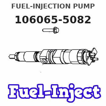
ZEXEL
106065-5082
1060655082
Rating:
Scheme ###:
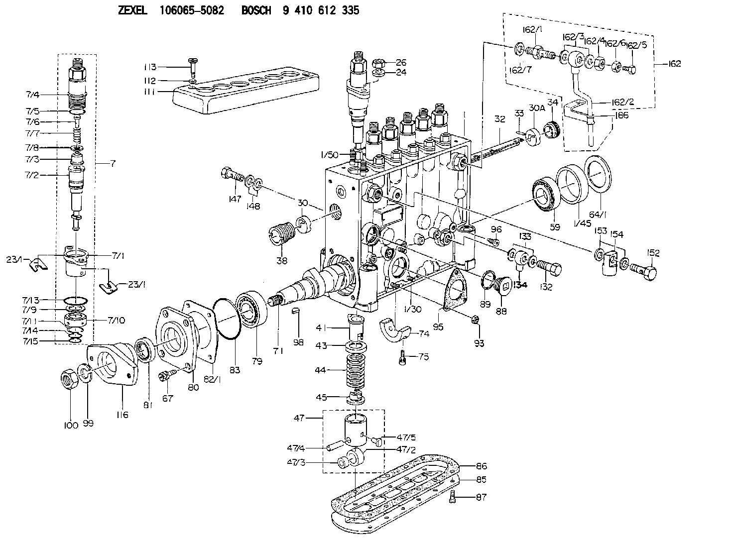
| 1. | [1] | 134000-8221 | PUMP HOUSING |
| 1/30. | [3] | 029040-6020 | STUD |
| 1/45. | [1] | 134311-0000 | SPACER RING |
| 1/50. | [12] | 134138-0000 | STUD |
| 7. | [6] | 134150-5020 | PLUNGER-AND-BARREL ASSY |
| 7/1. | [1] | 134131-1920 | FLANGE BUSHING |
| 7/2. | [1] | 134101-2820 | PLUNGER-AND-BARREL ASSY |
| 7/3. | [1] | 134110-0220 | DELIVERY-VALVE ASSEMBLY |
| 7/4. | [1] | 134116-2900 | FITTING |
| 7/5. | [1] | 029632-2070 | O-RING |
| 7/6. | [1] | 134117-0500 | FILLER PIECE |
| 7/7. | [1] | 132112-0200 | COILED SPRING |
| 7/8. | [1] | 134115-0100 | GASKET |
| 7/9. | [1] | 029302-0140 | PLAIN WASHER |
| 7/10. | [1] | 134135-0200 | CAPSULE |
| 7/11. | [1] | 029602-0010 | LOCKING WASHER |
| 7/13. | [1] | 139729-0100 | O-RING |
| 7/14. | [1] | 029631-5020 | O-RING |
| 7/15. | [1] | 029631-5020 | O-RING |
| 23/1. | [0] | 139400-0900 | SHIM T0.500 |
| 23/1. | [0] | 139400-1000 | SHIM T0.525 |
| 23/1. | [0] | 139400-1100 | SHIM T0.550 |
| 23/1. | [0] | 139400-1200 | SHIM T0.575 |
| 23/1. | [0] | 139400-1300 | SHIM T0.600 |
| 23/1. | [0] | 139400-1400 | SHIM T0.625 |
| 23/1. | [0] | 139400-1500 | SHIM T0.650 |
| 23/1. | [0] | 139400-1600 | SHIM T0.675 |
| 23/1. | [0] | 139400-1700 | SHIM T0.700 |
| 23/1. | [0] | 139400-1800 | SHIM T0.725 |
| 23/1. | [0] | 139400-1900 | SHIM T0.750 |
| 23/1. | [0] | 139400-2000 | SHIM T0.775 |
| 23/1. | [0] | 139400-2100 | SHIM T0.800 |
| 23/1. | [0] | 139400-2200 | SHIM T0.825 |
| 23/1. | [0] | 139400-2300 | SHIM T0.850 |
| 23/1. | [0] | 139400-2400 | SHIM T0.875 |
| 23/1. | [0] | 139400-2500 | SHIM T0.900 |
| 23/1. | [0] | 139400-2600 | SHIM T0.925 |
| 23/1. | [0] | 139400-2700 | SHIM T0.950 |
| 23/1. | [0] | 139400-2800 | SHIM T0.975 |
| 23/1. | [0] | 139400-2900 | SHIM T1.000 |
| 23/1. | [0] | 139400-3000 | SHIM T1.025 |
| 23/1. | [0] | 139400-3100 | SHIM T1.050 |
| 23/1. | [0] | 139400-3200 | SHIM T1.075 |
| 23/1. | [0] | 139400-3300 | SHIM T1.100 |
| 23/1. | [0] | 139400-3400 | SHIM T1.125 |
| 23/1. | [0] | 139400-3500 | SHIM T1.150 |
| 23/1. | [0] | 139400-3600 | SHIM T1.175 |
| 23/1. | [0] | 139400-3700 | SHIM T1.200 |
| 23/1. | [0] | 139400-3800 | SHIM T1.225 |
| 23/1. | [0] | 139400-3800 | SHIM T1.225 |
| 23/1. | [0] | 139400-3900 | SHIM T1.250 |
| 23/1. | [0] | 139400-4000 | SHIM T1.275 |
| 23/1. | [0] | 139400-4100 | SHIM T1.300 |
| 23/1. | [0] | 139400-4200 | SHIM T1.325 |
| 23/1. | [0] | 139400-4300 | SHIM T1.350 |
| 23/1. | [0] | 139400-4400 | SHIM T1.375 |
| 23/1. | [0] | 139400-4500 | SHIM T1.400 |
| 23/1. | [0] | 139400-4600 | SHIM T1.425 |
| 23/1. | [0] | 139400-4700 | SHIM T1.450 |
| 23/1. | [0] | 139400-4800 | SHIM T1.475 |
| 23/1. | [0] | 139400-4900 | SHIM T1.500 |
| 23/1. | [0] | 139400-5000 | SHIM T1.525 |
| 23/1. | [0] | 139400-5100 | SHIM T1.550 |
| 23/1. | [0] | 139400-5200 | SHIM T1.575 |
| 23/1. | [0] | 139400-5300 | SHIM T1.600 |
| 23/1. | [0] | 139400-5400 | SHIM T1.625 |
| 23/1. | [0] | 139400-5500 | SHIM T1.650 |
| 23/1. | [0] | 139400-5600 | SHIM T1.675 |
| 23/1. | [0] | 139400-5700 | SHIM T1.700 |
| 23/1. | [0] | 139400-5800 | SHIM T1.725 |
| 23/1. | [0] | 139400-5900 | SHIM T1.750 |
| 23/1. | [0] | 139400-6000 | SHIM T1.775 |
| 23/1. | [0] | 139400-6100 | SHIM T1.800 |
| 23/1. | [0] | 139400-6200 | SHIM T1.825 |
| 23/1. | [0] | 139400-6300 | SHIM T1.850 |
| 23/1. | [0] | 139400-6400 | SHIM T1.875 |
| 23/1. | [0] | 139400-6500 | SHIM T1.900 |
| 23/1. | [0] | 139400-6600 | SHIM T1.925 |
| 23/1. | [0] | 139400-6700 | SHIM T1.950 |
| 23/1. | [0] | 139400-6800 | SHIM T1.975 |
| 24. | [12] | 134132-0300 | PLAIN WASHER D20&11T2.5 |
| 26. | [12] | 013021-0040 | UNION NUT M10P1.5H8 |
| 30. | [1] | 134001-0200 | BUSHING |
| 30A. | [1] | 134001-0000 | BUSHING |
| 32. | [1] | 134256-1500 | CONTROL RACK |
| 33. | [1] | 024030-2030 | BEARING PIN |
| 34. | [1] | 134222-0000 | BUSHING |
| 38. | [1] | 134222-0500 | BUSHING |
| 41. | [6] | 134241-0021 | CONTROL SLEEVE |
| 43. | [6] | 134216-0000 | SLOTTED WASHER |
| 44. | [6] | 134215-0300 | COMPRESSION SPRING |
| 45. | [6] | 134217-0500 | SLOTTED WASHER |
| 47. | [6] | 134200-0020 | TAPPET |
| 47/2. | [1] | 134204-0000 | ROLLER |
| 47/3. | [1] | 134205-0000 | BUSHING |
| 47/4. | [1] | 134203-0000 | BEARING PIN |
| 47/5. | [1] | 131206-0500 | SLIDER |
| 59. | [1] | 016650-2230 | BEARING PLATE |
| 64/1. | [0] | 134303-0000 | SHIM D59.8&43T1.2 |
| 64/1. | [0] | 134303-0100 | SHIM D59.8&43T1.5 |
| 64/1. | [0] | 134303-0200 | SHIM D59.8&43T1.8 |
| 64/1. | [0] | 134303-0300 | SHIM D59.8&43T2.0 |
| 64/1. | [0] | 134303-0400 | SHIM D59.8&43T0.6 |
| 67. | [4] | 029010-6810 | BLEEDER SCREW |
| 71. | [1] | 134371-0900 | CAMSHAFT |
| 74. | [1] | 134306-0100 | BEARING SHELL |
| 75. | [2] | 020106-2040 | BLEEDER SCREW M6P1L20 |
| 79. | [1] | 016650-2230 | BEARING PLATE |
| 80. | [1] | 134316-0700 | COVER |
| 81. | [1] | 026712-5010 | PACKING RING |
| 82/1. | [0] | 134314-0000 | SHIM T0.1 |
| 82/1. | [0] | 134314-0100 | SHIM T0.12 |
| 82/1. | [0] | 134314-0200 | SHIM T0.14 |
| 82/1. | [0] | 134314-0300 | SHIM T0.16 |
| 82/1. | [0] | 134314-0400 | SHIM T0.18 |
| 82/1. | [0] | 134314-0500 | SHIM T0.3 |
| 82/1. | [0] | 134314-0600 | SHIM T0.5 |
| 83. | [1] | 029635-5010 | O-RING |
| 85. | [1] | 134043-0800 | COVER |
| 86. | [1] | 134042-1400 | GASKET |
| 87. | [12] | 012206-1640 | FLAT-HEAD SCREW M6P1L16 |
| 88. | [1] | 134045-0100 | CAPSULE |
| 89. | [1] | 026524-2940 | GASKET D28.9&24.3T2 |
| 93. | [3] | 139206-0400 | UNION NUT |
| 95. | [1] | 131041-0800 | GASKET |
| 96. | [6] | 134047-0000 | CAPSULE |
| 98. | [1] | 025805-1910 | WOODRUFF KEY |
| 99. | [1] | 014111-8440 | LOCKING WASHER |
| 100. | [1] | 013121-8140 | UNION NUT M18P1.5H15 |
| 111. | [1] | 134416-0100 | COVER |
| 112. | [2] | 014530-6540 | TAB WASHER |
| 113. | [2] | 021306-3010 | FLAT-HEAD SCREW |
| 116. | [1] | 156612-9800 | COUPLING PLATE |
| 132. | [1] | 131601-3600 | BLEEDER SCREW |
| 133. | [2] | 026514-1840 | GASKET D17.9&14.2T1 |
| 134. | [1] | 134441-0500 | INLET UNION |
| 147. | [1] | 131601-4300 | EYE BOLT |
| 148. | [2] | 026510-1340 | GASKET D13.4&10.2T1 |
| 152. | [1] | 131601-3600 | BLEEDER SCREW |
| 153. | [2] | 026514-1840 | GASKET D17.9&14.2T1 |
| 154. | [1] | 029711-4500 | INLET UNION |
| 162. | [1] | 132444-3720 | AIR FILTER |
| 162/1. | [1] | 132441-0200 | SPRING SEAT |
| 162/2. | [1] | 134442-0320 | PIPE |
| 162/3. | [2] | 026512-1540 | GASKET D15.4&12.2T1.50 |
| 162/4. | [1] | 029241-2020 | UNION NUT |
| 162/5. | [1] | 132444-0300 | BLEEDER SCREW |
| 162/6. | [1] | 023020-8040 | UNION NUT M8P1H5 |
| 162/7. | [1] | 026512-1540 | GASKET D15.4&12.2T1.50 |
| 186. | [1] | 134447-0400 | CLAMPING BAND |
Cross reference number
Zexel num
Bosch num
Firm num
Name
Information:
preparatory steps: a) remove flywheel housingb) remove timing gear coverc) remove pistons1. Lay the engine on its side or top in a suitable stand.2. Attach a hoist to the crankshaft. 3. Remove the main bearing caps (1). 4. Remove the crankshaft-weight 200 lbs. (91 kg).5. Remove the crankshaft main bearings from the cylinder block and main bearing caps.
If the main bearings are not going to be replaced mark them with respect to their location in the engine.
6. Using tool setup (A), remove the crankshaft gear and oil seal wear sleeve.Install Crankshaft
1. Heat the crankshaft gear and the oil seal wear sleeve, maximum 600°F (316°C), and install them on the crankshaft.2. Clean the bearing seating surfaces in the cylinder block and the main bearing caps. Install the upper and lower halves of the bearings in the cylinder block bearing caps. Lubricate the bearings with clean SAE 30 engine oil.
If the main bearings are not being replaced the original bearings must be installed in the same location they were removed from.
3. Attach a hoist and position the crankshaft in the cylinder block with the timing marks (1) aligned. 4. Using wire (A), check the main bearing clearance. Install the caps in the respective positions with the number stamped on cap facing the corresponding number cast on side of the cylinder block web. 5. Lubricate the threads of bearing cap retaining bolts and face of washers with clean SAE 30 engine oil. Install the retaining bolts and washers. Tighten both bolts to 30 3 lb. ft. (4,1 0,4 mkg). Mark both bolt heads and bearing caps then tighten each bolt an additional 90° from mark. Remove bearing caps and measure thickness of wire (A). Main bearing clearance should be .0030-.0059 in. (0,076-0,150 mm).6. Lubricate the lower halves of main bearings with clean SAE 30 engine oil. Install main bearing caps in their respective positions. Install cap retaining bolts and washers. Tighten both bolts to 30 3 lb. ft. (4,1 0,4 mkg). Mark both bolt heads and bearing caps then tighten each bolt an additional 90° from mark. 7. Using tool setup (B), check the crankshaft end play as controlled by thrust bearing (2) on rear main bearing. End play should be .0025-.0145 in. (0,064-0,368 mm). Maximum permissible end play is .025 in. (0,64 mm).concluding steps: a) install pistonsb) install timing gear coverc) install flywheel housingd) check fuel injection pump timing. See REMOVE AND INSTALL FUEL INJECTION PUMP HOUSING AND GOVERNOR AS A UNIT.