Information fuel-injection pump
BOSCH
9 410 612 971
9410612971
ZEXEL
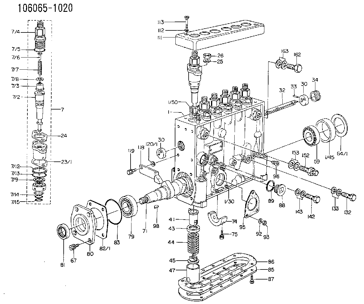
106065-1020
1060651020
Rating:
Scheme ###:
| 1. | [1] | 134050-9620 | PUMP HOUSING |
| 1/30. | [3] | 029040-6020 | STUD |
| 1/45. | [1] | 134311-0000 | SPACER RING |
| 1/50. | [12] | 134138-0000 | STUD |
| 7. | [6] | 134130-0320 | PLUNGER-AND-BARREL ASSY |
| 7/1. | [6] | 134131-0520 | FLANGE BUSHING |
| 7/2. | [6] | 134101-1420 | PLUNGER-AND-BARREL ASSY |
| 7/3. | [6] | 134110-0120 | DELIVERY-VALVE ASSEMBLY |
| 7/4. | [6] | 134116-0700 | FITTING |
| 7/5. | [6] | 029632-2070 | O-RING |
| 7/6. | [6] | 134117-0500 | FILLER PIECE |
| 7/7. | [6] | 132112-0200 | COILED SPRING |
| 7/8. | [6] | 134115-0100 | GASKET |
| 7/9. | [6] | 029302-0140 | PLAIN WASHER |
| 7/10. | [6] | 134135-0200 | CAPSULE |
| 7/11. | [6] | 029602-0010 | LOCKING WASHER |
| 7/12. | [6] | 134137-0000 | SPACER RING |
| 7/13. | [6] | 029632-9030 | O-RING |
| 7/14. | [6] | 029631-5020 | O-RING |
| 7/15. | [6] | 029631-5020 | O-RING |
| 23/1. | [0] | 134139-0000 | SHIM T0.5 |
| 23/1. | [0] | 134139-0100 | SHIM T0.6 |
| 23/1. | [0] | 134139-0200 | SHIM T0.7 |
| 23/1. | [0] | 134139-0300 | SHIM T0.8 |
| 23/1. | [0] | 134139-0400 | SHIM T0.9 |
| 23/1. | [0] | 134139-0500 | SHIM T0.4 |
| 23/1. | [0] | 134139-0600 | SHIM T0.15 |
| 23/1. | [0] | 134139-2300 | SHIM T1.5 |
| 24. | [6] | 134132-0100 | PLAIN WASHER |
| 25. | [12] | 014111-0440 | LOCKING WASHER |
| 26. | [12] | 013021-0040 | UNION NUT M10P1.5H8 |
| 30. | [2] | 134001-0000 | BUSHING |
| 30. | [2] | 134001-0000 | BUSHING |
| 32. | [1] | 134256-0000 | CONTROL RACK |
| 33. | [1] | 024030-2030 | BEARING PIN |
| 34. | [1] | 134222-0000 | BUSHING |
| 41. | [6] | 134241-0021 | CONTROL SLEEVE |
| 43. | [6] | 134216-0000 | SLOTTED WASHER |
| 44. | [6] | 134215-0300 | COMPRESSION SPRING |
| 45. | [6] | 134217-0500 | SLOTTED WASHER |
| 47. | [6] | 134200-0020 | TAPPET |
| 47/2. | [1] | 134204-0000 | ROLLER |
| 47/3. | [1] | 134205-0000 | BUSHING |
| 47/4. | [1] | 134203-0000 | BEARING PIN |
| 47/5. | [1] | 131206-0500 | SLIDER |
| 59. | [1] | 016650-2230 | BEARING PLATE |
| 59B. | [1] | 028222-5010 | BEARING PLATE |
| 64/1. | [0] | 134303-0000 | SHIM D59.8&43T1.2 |
| 64/1. | [0] | 134303-0100 | SHIM D59.8&43T1.5 |
| 64/1. | [0] | 134303-0200 | SHIM D59.8&43T1.8 |
| 64/1. | [0] | 134303-0300 | SHIM D59.8&43T2.0 |
| 64/1. | [0] | 134303-0400 | SHIM D59.8&43T0.6 |
| 67. | [4] | 029010-6810 | BLEEDER SCREW |
| 71. | [1] | 134370-0000 | CAMSHAFT |
| 74. | [1] | 134306-0000 | BEARING SHELL |
| 75. | [2] | 020106-2040 | BLEEDER SCREW M6P1L20 |
| 79. | [1] | 016650-2230 | BEARING PLATE |
| 79B. | [1] | 028222-5010 | BEARING PLATE |
| 80. | [1] | 134330-0000 | COVER |
| 81. | [1] | 029622-0140 | PACKING RING |
| 82/1. | [0] | 134314-0000 | SHIM T0.1 |
| 82/1. | [0] | 134314-0100 | SHIM T0.12 |
| 82/1. | [0] | 134314-0200 | SHIM T0.14 |
| 82/1. | [0] | 134314-0300 | SHIM T0.16 |
| 82/1. | [0] | 134314-0400 | SHIM T0.18 |
| 82/1. | [0] | 134314-0500 | SHIM T0.3 |
| 82/1. | [0] | 134314-0600 | SHIM T0.5 |
| 83. | [1] | 029635-5010 | O-RING |
| 85. | [1] | 134043-0800 | COVER |
| 86. | [1] | 134042-1400 | GASKET |
| 87. | [12] | 012206-1640 | FLAT-HEAD SCREW M6P1L16 |
| 88. | [1] | 134045-0100 | CAPSULE |
| 89. | [1] | 026524-2940 | GASKET D28.9&24.3T2 |
| 93. | [3] | 139206-0400 | UNION NUT |
| 95. | [1] | 131041-0800 | GASKET |
| 96. | [6] | 134047-0000 | CAPSULE |
| 98. | [1] | 025804-1610 | WOODRUFF KEY |
| 111. | [1] | 134416-0100 | COVER |
| 112. | [2] | 014530-6540 | TAB WASHER |
| 113. | [2] | 021306-3010 | FLAT-HEAD SCREW |
| 118. | [1] | 134496-0800 | POINTER |
| 119. | [2] | 020006-1640 | BLEEDER SCREW M6P1L16 4T |
| 120/1. | [0] | 139400-0100 | SHIM T0.2 |
| 120/1. | [0] | 139400-0200 | SHIM T0.3 |
| 120/1. | [0] | 139400-0300 | SHIM T0.5 |
| 120/1. | [0] | 139400-0400 | SHIM T1.0 |
| 120/1. | [0] | 139400-7200 | SHIM T0.1 |
| 132. | [1] | 029731-4680 | EYE BOLT |
| 133. | [2] | 029331-4230 | GASKET |
| 142. | [1] | 029731-0430 | EYE BOLT |
| 143. | [2] | 026510-1340 | GASKET D13.4&10.2T1 |
| 152. | [1] | 132424-0620 | OVER FLOW VALVE |
| 153. | [2] | 026514-1840 | GASKET D17.9&14.2T1 |
| 162. | [1] | 029731-4680 | EYE BOLT |
| 163. | [2] | 026514-1840 | GASKET D17.9&14.2T1 |
Include in #1:
106651-0020
as FUEL INJECTION PUMP
Cross reference number
Zexel num
Bosch num
Firm num
Name
Information:
REMOVING CAM FOLLOWERS WITH MAGNET2. Rotate the crankshaft CLOCKWISE (as viewed from front of engine) until the timing mark on crankshaft gear is aligned with timing mark on camshaft large gear.3. Remove the plug from timing pin hole in fuel injection pump housing and install timing pin (1).4. Remove the tachometer drive adapter housing.5. On engines equipped with the hydraulic governor; Remove the automatic timing advance unit or the fuel injection pump camshaft drive gear by removing the tachometer drive shaft with a 9S5031 (5/8 in.) Deep Well Socket. Using puller group (2), thread the 9S8528 Bolt Assembly into the fuel injection pump camshaft. Do not force the bolt assembly. It should thread easily. Install the 9S8527 Bolt by threading it into the automatic timing advance unit or the fuel injection pump camshaft drive gear. Then tighten the 9S8527 Bolt with a wrench until the automatic timing advance unit or fuel injection pump camshaft drive gear "pops" loose.On engines equipped with the "Max-Min" governor; Loosen the automatic timing advance unit retaining bolt with a 8S2357 (9/16in.) Deep Well Socket. The bolt will first feel loose, then it will tighten again when the taper drive of the automatic timing advance unit starts to separate from the camshaft.
TIMING PIN AND PULLER INSTALLED
1. FT887 Timing Pin (Fabricated Tool). 2. 9S8520 Puller Group.6. Remove the camshaft thrust pin (3) from the rear of the cylinder block.
REMOVING THRUST PIN
3. Thrust pin.7. Pull the camshaft (4) out of the cylinder block, being careful to not damage the camshaft bearings or journals.
REMOVING CAMSHAFT
4. Camshaft.Install Camshaft
1. Lubricate the camshaft bearing surfaces with clean engine oil (SAE 30).2. Install the camshaft with timing mark on camshaft gear aligned with timing mark on crankshaft gear.3. Install the camshaft thrust pin in rear of cylinder block. Tighten the thrust pin to 35 5 lb. ft. (4.8 0.7 mkg).4. Position the automatic timing advance unit or fuel injection pump drive gear on the fuel injection pump camshaft. Install the tachometer drive shaft. Engines equipped with the hydraulic governor; Tighten retaining bolt to 32 2 lb. ft. (4.4 0.3 mkg). Engines equipped with the "Max-Min" governor; Tighten retaining bolt to 35 2 lb. ft. (4.8 0.3 mkg).5. Remove timing pin from fuel injection pump housing and install plug in timing pin hole.6. Install the cam followers in the same location from which they were removed. Always use new cam followers with a new camshaft. Be sure to put clean engine oil on the cam followers and camshaft lobes before installing the cam followers.