Information fuel-injection pump
BOSCH
9 410 611 560
9410611560
ZEXEL
106061-7040
1060617040
MITSUBISHI
3256534320
3256534320
Rating:
Scheme ###:
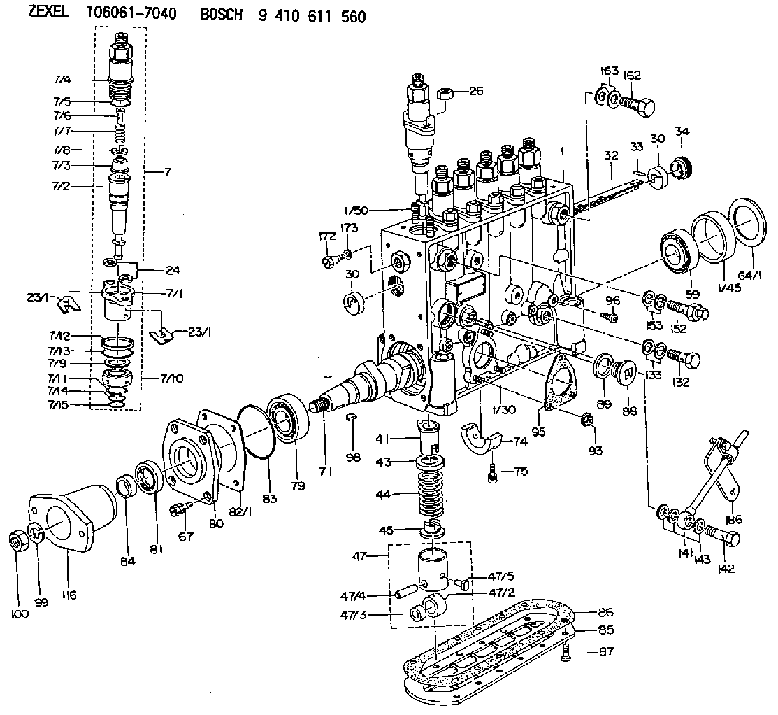
| 1. | [1] | 134051-5420 | PUMP HOUSING |
| 1/30. | [3] | 029040-6020 | STUD |
| 1/45. | [1] | 134311-0000 | SPACER RING |
| 1/50. | [12] | 134138-0000 | STUD |
| 7. | [6] | 134143-9820 | PLUNGER-AND-BARREL ASSY |
| 7/1. | [6] | 134131-1020 | FLANGE BUSHING |
| 7/2. | [6] | 134151-3620 | PLUNGER-AND-BARREL ASSY |
| 7/3. | [6] | 134110-4820 | DELIVERY-VALVE ASSEMBLY |
| 7/4. | [6] | 134116-4820 | FITTING |
| 7/5. | [6] | 029632-2070 | O-RING |
| 7/6. | [6] | 134117-0500 | FILLER PIECE |
| 7/7. | [6] | 134112-1600 | COILED SPRING |
| 7/8. | [6] | 134115-0100 | GASKET |
| 7/9. | [6] | 029302-0140 | PLAIN WASHER |
| 7/10. | [6] | 134135-0200 | CAPSULE |
| 7/11. | [6] | 029602-0010 | LOCKING WASHER |
| 7/12. | [6] | 134137-0100 | SPACER RING |
| 7/13. | [6] | 029632-9030 | O-RING |
| 7/14. | [6] | 029631-5020 | O-RING |
| 7/15. | [6] | 029631-5020 | O-RING |
| 23/1. | [0] | 139400-0900 | SHIM T0.500 |
| 23/1. | [0] | 139400-1000 | SHIM T0.525 |
| 23/1. | [0] | 139400-1100 | SHIM T0.550 |
| 23/1. | [0] | 139400-1200 | SHIM T0.575 |
| 23/1. | [0] | 139400-1300 | SHIM T0.600 |
| 23/1. | [0] | 139400-1400 | SHIM T0.625 |
| 23/1. | [0] | 139400-1500 | SHIM T0.650 |
| 23/1. | [0] | 139400-1600 | SHIM T0.675 |
| 23/1. | [0] | 139400-1700 | SHIM T0.700 |
| 23/1. | [0] | 139400-1800 | SHIM T0.725 |
| 23/1. | [0] | 139400-1900 | SHIM T0.750 |
| 23/1. | [0] | 139400-2000 | SHIM T0.775 |
| 23/1. | [0] | 139400-2100 | SHIM T0.800 |
| 23/1. | [0] | 139400-2200 | SHIM T0.825 |
| 23/1. | [0] | 139400-2300 | SHIM T0.850 |
| 23/1. | [0] | 139400-2400 | SHIM T0.875 |
| 23/1. | [0] | 139400-2500 | SHIM T0.900 |
| 23/1. | [0] | 139400-2600 | SHIM T0.925 |
| 23/1. | [0] | 139400-2700 | SHIM T0.950 |
| 23/1. | [0] | 139400-2800 | SHIM T0.975 |
| 23/1. | [0] | 139400-2900 | SHIM T1.000 |
| 23/1. | [0] | 139400-3000 | SHIM T1.025 |
| 23/1. | [0] | 139400-3100 | SHIM T1.050 |
| 23/1. | [0] | 139400-3200 | SHIM T1.075 |
| 23/1. | [0] | 139400-3300 | SHIM T1.100 |
| 23/1. | [0] | 139400-3400 | SHIM T1.125 |
| 23/1. | [0] | 139400-3500 | SHIM T1.150 |
| 23/1. | [0] | 139400-3600 | SHIM T1.175 |
| 23/1. | [0] | 139400-3700 | SHIM T1.200 |
| 23/1. | [0] | 139400-3800 | SHIM T1.225 |
| 23/1. | [0] | 139400-3900 | SHIM T1.250 |
| 23/1. | [0] | 139400-4000 | SHIM T1.275 |
| 23/1. | [0] | 139400-4100 | SHIM T1.300 |
| 23/1. | [0] | 139400-4200 | SHIM T1.325 |
| 23/1. | [0] | 139400-4300 | SHIM T1.350 |
| 23/1. | [0] | 139400-4400 | SHIM T1.375 |
| 23/1. | [0] | 139400-4500 | SHIM T1.400 |
| 23/1. | [0] | 139400-4600 | SHIM T1.425 |
| 23/1. | [0] | 139400-4700 | SHIM T1.450 |
| 23/1. | [0] | 139400-4800 | SHIM T1.475 |
| 23/1. | [0] | 139400-4900 | SHIM T1.500 |
| 23/1. | [0] | 139400-5000 | SHIM T1.525 |
| 23/1. | [0] | 139400-5100 | SHIM T1.550 |
| 23/1. | [0] | 139400-5200 | SHIM T1.575 |
| 23/1. | [0] | 139400-5300 | SHIM T1.600 |
| 23/1. | [0] | 139400-5400 | SHIM T1.625 |
| 23/1. | [0] | 139400-5500 | SHIM T1.650 |
| 23/1. | [0] | 139400-5600 | SHIM T1.675 |
| 23/1. | [0] | 139400-5700 | SHIM T1.700 |
| 23/1. | [0] | 139400-5800 | SHIM T1.725 |
| 23/1. | [0] | 139400-5900 | SHIM T1.750 |
| 23/1. | [0] | 139400-6000 | SHIM T1.775 |
| 23/1. | [0] | 139400-6100 | SHIM T1.800 |
| 23/1. | [0] | 139400-6200 | SHIM T1.825 |
| 23/1. | [0] | 139400-6300 | SHIM T1.850 |
| 23/1. | [0] | 139400-6300 | SHIM T1.850 |
| 23/1. | [0] | 139400-6400 | SHIM T1.875 |
| 23/1. | [0] | 139400-6500 | SHIM T1.900 |
| 23/1. | [0] | 139400-6600 | SHIM T1.925 |
| 23/1. | [0] | 139400-6700 | SHIM T1.950 |
| 23/1. | [0] | 139400-6800 | SHIM T1.975 |
| 24. | [12] | 134132-0300 | PLAIN WASHER D20&11T2.5 |
| 26. | [12] | 013021-0040 | UNION NUT M10P1.5H8 |
| 30. | [2] | 134001-0000 | BUSHING |
| 30. | [2] | 134001-0000 | BUSHING |
| 32. | [1] | 134256-0000 | CONTROL RACK |
| 33. | [1] | 024030-2030 | BEARING PIN |
| 34. | [1] | 134222-0000 | BUSHING |
| 41. | [6] | 134241-0320 | CONTROL SLEEVE |
| 43. | [6] | 134216-0000 | SLOTTED WASHER |
| 44. | [6] | 134215-0700 | COILED SPRING |
| 45. | [6] | 134217-0500 | SLOTTED WASHER |
| 47. | [6] | 134200-0420 | TAPPET |
| 47/2. | [1] | 134204-0100 | ROLLER |
| 47/3. | [1] | 134205-0000 | BUSHING |
| 47/4. | [1] | 134203-0000 | BEARING PIN |
| 47/5. | [1] | 131206-0500 | SLIDER |
| 59. | [1] | 016650-2230 | BEARING PLATE |
| 64/1. | [0] | 134303-0000 | SHIM D59.8&43T1.2 |
| 64/1. | [0] | 134303-0100 | SHIM D59.8&43T1.5 |
| 64/1. | [0] | 134303-0200 | SHIM D59.8&43T1.8 |
| 64/1. | [0] | 134303-0300 | SHIM D59.8&43T2.0 |
| 64/1. | [0] | 134303-0400 | SHIM D59.8&43T0.6 |
| 67. | [4] | 029010-6810 | BLEEDER SCREW |
| 71. | [1] | 134371-4900 | CAMSHAFT |
| 74. | [1] | 134306-0300 | BEARING SHELL |
| 75. | [2] | 020106-2040 | BLEEDER SCREW M6P1L20 |
| 79. | [1] | 016650-2230 | BEARING PLATE |
| 80. | [1] | 134316-1700 | COVER |
| 81. | [1] | 139625-0000 | PACKING RING |
| 82/1. | [0] | 134314-0000 | SHIM T0.1 |
| 82/1. | [0] | 134314-0100 | SHIM T0.12 |
| 82/1. | [0] | 134314-0200 | SHIM T0.14 |
| 82/1. | [0] | 134314-0300 | SHIM T0.16 |
| 82/1. | [0] | 134314-0400 | SHIM T0.18 |
| 82/1. | [0] | 134314-0500 | SHIM T0.3 |
| 82/1. | [0] | 134314-0600 | SHIM T0.5 |
| 83. | [1] | 029635-5010 | O-RING |
| 84. | [1] | 134563-0900 | SLIDING PIECE |
| 85. | [1] | 134043-0800 | COVER |
| 86. | [1] | 134042-1400 | GASKET |
| 87. | [12] | 012206-1640 | FLAT-HEAD SCREW M6P1L16 |
| 88. | [1] | 134045-0100 | CAPSULE |
| 89. | [1] | 026524-2940 | GASKET D28.9&24.3T2 |
| 93. | [3] | 139206-0400 | UNION NUT |
| 95. | [1] | 131041-0800 | GASKET |
| 96. | [6] | 134047-0000 | CAPSULE |
| 98. | [1] | 029470-5010 | WOODRUFF KEY |
| 99. | [1] | 023641-8410 | LOCKING WASHER |
| 100. | [1] | 134325-0700 | UNION NUT |
| 116. | [1] | 156636-7500 | COUPLING PLATE |
| 132. | [1] | 029731-4680 | EYE BOLT |
| 133. | [2] | 029341-4130 | GASKET D20&13.8T2* |
| 141. | [1] | 134433-4820 | PIPE |
| 142. | [1] | 029731-0490 | EYE BOLT |
| 143. | [3] | 029341-0110 | GASKET |
| 152. | [1] | 131424-7420 | OVER FLOW VALVE |
| 153. | [2] | 029341-4130 | GASKET D20&13.8T2* |
| 162. | [1] | 029731-4570 | EYE BOLT |
| 163. | [2] | 029341-4130 | GASKET D20&13.8T2* |
| 172. | [1] | 131420-0400 | BLEEDER SCREW |
| 173. | [1] | 026506-1040 | GASKET D9.9&6.2T1 |
| 186. | [1] | 134510-8220 | BRACKET |
Cross reference number
Zexel num
Bosch num
Firm num
Name
Information:
Use 5P3519 Piston Ring Groove Gauge to check top and intermediate ring grooves with straight sides. For instructions on the use of the gauge, see the GUIDELINE FOR REUSABLE PARTS; PISTONS AND CYLINDER LINERS, Form No. SEBF8001.1P435 Piston Assembly
Maximum permissible clearance between ring and groove (all rings) ... .014 in.(0.36 mm)(1) Clearance between top ring and groove ... .0057 to .0071 in.(0.145 to 0.180 mm)(2) Clearance between center ring and groove ... .0030 to .0048 in.(0.076 to 0.122 mm)(3) Clearance between oil ring and groove ... .0015 to .0030 in.(0.038 to 0.076 mm)(4) Bore in piston for pin ... 2.0005 .0002 in.(50.813 0.005 mm) Clearance between pin and bore in piston (new) ... .0003 to .0010 in.(0.008 to 0.025 mm)Maximum permissible clearance between piston pin and bore in piston (worn) ... .002 in.(0.05 mm)Clearance between ends of piston ring, installed in cylinder liner with bore size of ... 5.400 to 5.402 in.(137.16 to 137.21 mm)*(5) Top ring ... .019 to .029 in.(0.48 to 0.74 mm)(6) Center ring ... .019 to .029 in.(0.48 to 0.74 mm)(7) Oil ring ... .015 to .025 in.(0.38 to 0.64 mm) ... .003 in.(0.08 mm)*Increase in clearance between ends of piston rings for each .001 in. (0.03 mm) increase in size of bore of the cylinder liner 9S2266 Piston Assembly
Maximum permissible clearance between ring and groove (all rings) ... .006 in.(0.15 mm)(1) Clearance between top ring and groove ... .0055 to .0073 in.(0.140 to 0.185 mm)(2) Clearance between center ring and groove ... .0030 to .0048 in.(0.076 to 0.122 mm)(3) Clearance between oil ring and groove ... .0015 to .0030 in.(0.038 to 0.076 mm)(4) Bore in piston for pin ... 2.0005 .0002 in.(50.813 0.005 mm) Clearance between pin and bore in piston ... .0003 to .0010 in.(0.008 to 0.025 mm)Maximum permissible clearance between piston pin and bore in piston ... .002 in.(0.05 mm)Clearance between ends of piston ring, installed in cylinder liner with bore size of ... 5.400 to 5.402 in.(137.16 to 173.21 mm)*(5) Top ring ... .021 to .027 in.(0.53 to 0.69 mm)(6) Center ring ... .019 to .029 in.(0.48 to 0.74 mm)(7) Oil ring ... .015 to .025 in.(0.38 to 0.64 mm) ... .003 in.(0.08 mm)*Increase in clearance between ends of piston rings for each .001 in. (0.03 mm) increase in size of bore of the cylinder liner 9L6054 And 9N2875 Piston Assemblies
Make reference to GUIDELINE FOR REUSABLE PARTS; PISTONS AND CYLINDER LINERS, Form No. SEBF8001. (4) Bore in piston for pin ... 2.0005 .0002 in.(50.81 0.005 mm) Clearance between pin and bore in piston ... .0007 .0004 in.(0.018 0.010 mm)Maximum permissible clearance (worn) ... .002 in.(0.05 mm)Pin diameter ... 1.9998 .0002 in.(50.795 0.005 mm) When installed in the engine, the "V" mark on top of the piston must be in alignment with the "V"