Information fuel-injection pump
BOSCH
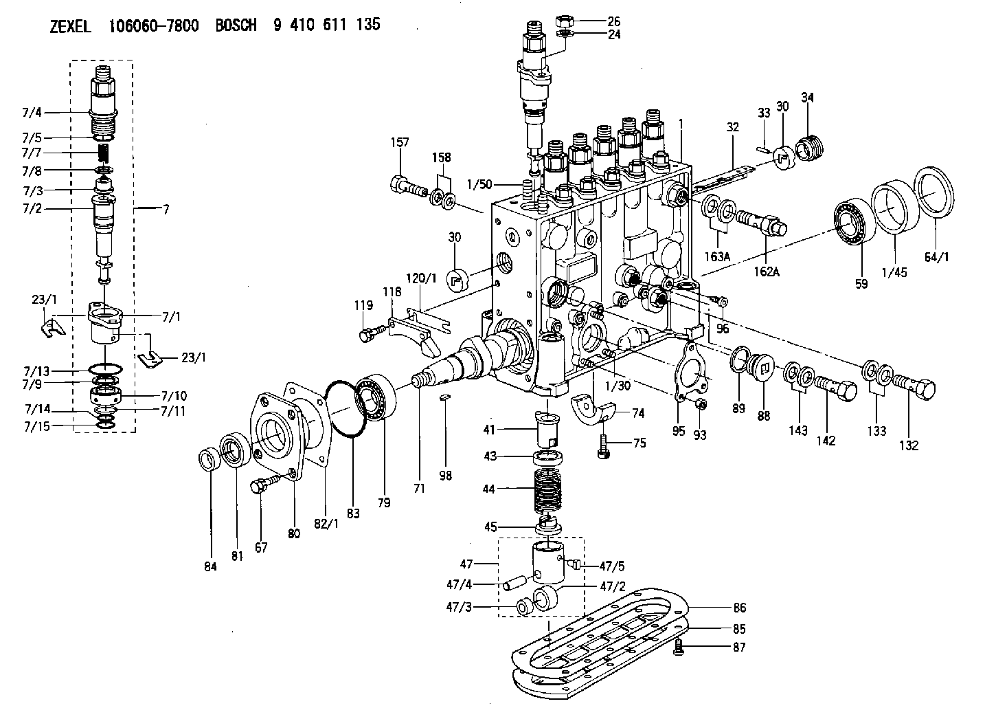
9 410 611 135
9410611135
ZEXEL
106060-7800
1060607800
HINO
221202140A
221202140a

Rating:
Scheme ###:
| 1. | [1] | 134051-1720 | PUMP HOUSING |
| 1/30. | [3] | 029040-6020 | STUD |
| 1/45. | [1] | 134311-0000 | SPACER RING |
| 1/50. | [12] | 134138-0000 | STUD |
| 7. | [6] | 134143-0020 | PLUNGER-AND-BARREL ASSY |
| 7/1. | [6] | 134131-1920 | FLANGE BUSHING |
| 7/2. | [6] | 134101-9620 | PLUNGER-AND-BARREL ASSY P78 |
| 7/3. | [6] | 134110-1420 | DELIVERY-VALVE ASSEMBLY P13 |
| 7/4. | [6] | 134116-2520 | FITTING |
| 7/5. | [6] | 139722-0400 | O-RING |
| 7/7. | [6] | 134112-0500 | COMPRESSION SPRING |
| 7/8. | [6] | 134115-0100 | GASKET |
| 7/9. | [6] | 029302-0140 | PLAIN WASHER |
| 7/10. | [6] | 134135-0400 | CAPSULE |
| 7/11. | [6] | 029602-0010 | LOCKING WASHER |
| 7/13. | [6] | 139729-0400 | O-RING |
| 7/14. | [6] | 139715-0400 | O-RING |
| 7/15. | [6] | 139715-0400 | O-RING |
| 23/1. | [0] | 139400-0900 | SHIM T0.500 |
| 23/1. | [0] | 139400-1000 | SHIM T0.525 |
| 23/1. | [0] | 139400-1100 | SHIM T0.550 |
| 23/1. | [0] | 139400-1200 | SHIM T0.575 |
| 23/1. | [0] | 139400-1300 | SHIM T0.600 |
| 23/1. | [0] | 139400-1400 | SHIM T0.625 |
| 23/1. | [0] | 139400-1500 | SHIM T0.650 |
| 23/1. | [0] | 139400-1600 | SHIM T0.675 |
| 23/1. | [0] | 139400-1700 | SHIM T0.700 |
| 23/1. | [0] | 139400-1800 | SHIM T0.725 |
| 23/1. | [0] | 139400-1900 | SHIM T0.750 |
| 23/1. | [0] | 139400-2000 | SHIM T0.775 |
| 23/1. | [0] | 139400-2100 | SHIM T0.800 |
| 23/1. | [0] | 139400-2200 | SHIM T0.825 |
| 23/1. | [0] | 139400-2300 | SHIM T0.850 |
| 23/1. | [0] | 139400-2400 | SHIM T0.875 |
| 23/1. | [0] | 139400-2500 | SHIM T0.900 |
| 23/1. | [0] | 139400-2600 | SHIM T0.925 |
| 23/1. | [0] | 139400-2700 | SHIM T0.950 |
| 23/1. | [0] | 139400-2800 | SHIM T0.975 |
| 23/1. | [0] | 139400-2900 | SHIM T1.000 |
| 23/1. | [0] | 139400-3000 | SHIM T1.025 |
| 23/1. | [0] | 139400-3100 | SHIM T1.050 |
| 23/1. | [0] | 139400-3200 | SHIM T1.075 |
| 23/1. | [0] | 139400-3300 | SHIM T1.100 |
| 23/1. | [0] | 139400-3400 | SHIM T1.125 |
| 23/1. | [0] | 139400-3500 | SHIM T1.150 |
| 23/1. | [0] | 139400-3600 | SHIM T1.175 |
| 23/1. | [0] | 139400-3700 | SHIM T1.200 |
| 23/1. | [0] | 139400-3800 | SHIM T1.225 |
| 23/1. | [0] | 139400-3900 | SHIM T1.250 |
| 23/1. | [0] | 139400-4000 | SHIM T1.275 |
| 23/1. | [0] | 139400-4100 | SHIM T1.300 |
| 23/1. | [0] | 139400-4200 | SHIM T1.325 |
| 23/1. | [0] | 139400-4300 | SHIM T1.350 |
| 23/1. | [0] | 139400-4400 | SHIM T1.375 |
| 23/1. | [0] | 139400-4500 | SHIM T1.400 |
| 23/1. | [0] | 139400-4600 | SHIM T1.425 |
| 23/1. | [0] | 139400-4700 | SHIM T1.450 |
| 23/1. | [0] | 139400-4800 | SHIM T1.475 |
| 23/1. | [0] | 139400-4900 | SHIM T1.500 |
| 23/1. | [0] | 139400-5000 | SHIM T1.525 |
| 23/1. | [0] | 139400-5100 | SHIM T1.550 |
| 23/1. | [0] | 139400-5200 | SHIM T1.575 |
| 23/1. | [0] | 139400-5300 | SHIM T1.600 |
| 23/1. | [0] | 139400-5400 | SHIM T1.625 |
| 23/1. | [0] | 139400-5500 | SHIM T1.650 |
| 23/1. | [0] | 139400-5600 | SHIM T1.675 |
| 23/1. | [0] | 139400-5700 | SHIM T1.700 |
| 23/1. | [0] | 139400-5800 | SHIM T1.725 |
| 23/1. | [0] | 139400-5900 | SHIM T1.750 |
| 23/1. | [0] | 139400-6000 | SHIM T1.775 |
| 23/1. | [0] | 139400-6100 | SHIM T1.800 |
| 23/1. | [0] | 139400-6200 | SHIM T1.825 |
| 23/1. | [0] | 139400-6300 | SHIM T1.850 |
| 23/1. | [0] | 139400-6400 | SHIM T1.875 |
| 23/1. | [0] | 139400-6500 | SHIM T1.900 |
| 23/1. | [0] | 139400-6600 | SHIM T1.925 |
| 23/1. | [0] | 139400-6600 | SHIM T1.925 |
| 23/1. | [0] | 139400-6700 | SHIM T1.950 |
| 23/1. | [0] | 139400-6800 | SHIM T1.975 |
| 24. | [12] | 134132-0300 | PLAIN WASHER |
| 26. | [12] | 013021-0040 | UNION NUT M10P1.5H8 |
| 30. | [2] | 134001-0000 | BUSHING |
| 30. | [2] | 134001-0000 | BUSHING |
| 32. | [1] | 134256-4500 | CONTROL RACK |
| 33. | [1] | 024030-2030 | BEARING PIN |
| 34. | [1] | 134222-0000 | BUSHING |
| 41. | [6] | 134241-0021 | CONTROL SLEEVE |
| 43. | [6] | 134216-0000 | SLOTTED WASHER |
| 44. | [6] | 134215-0400 | COMPRESSION SPRING |
| 45. | [6] | 134217-0500 | SLOTTED WASHER |
| 47. | [6] | 134200-0020 | TAPPET |
| 47/2. | [6] | 134204-0000 | ROLLER |
| 47/3. | [6] | 134205-0000 | BUSHING |
| 47/4. | [6] | 134203-0000 | BEARING PIN |
| 47/5. | [6] | 131206-0500 | SLIDER |
| 59. | [1] | 016650-2230 | BEARING PLATE 4T-32205(NSK) |
| 64/1. | [0] | 134303-0000 | SHIM D59.8&43T1.2 |
| 64/1. | [0] | 134303-0100 | SHIM D59.8&43T1.5 |
| 64/1. | [0] | 134303-0200 | SHIM D59.8&43T1.8 |
| 64/1. | [0] | 134303-0300 | SHIM D59.8&43T2.0 |
| 64/1. | [0] | 134303-0400 | SHIM D59.8&43T0.6 |
| 67. | [4] | 029010-6810 | BLEEDER SCREW |
| 71. | [1] | 134371-3500 | CAMSHAFT |
| 74. | [1] | 134306-0000 | BEARING SHELL |
| 75. | [2] | 020106-2040 | BLEEDER SCREW |
| 79. | [1] | 016650-2230 | BEARING PLATE 4T-32205(NSK) |
| 80. | [1] | 134316-1700 | COVER |
| 81. | [1] | 139625-0000 | PACKING RING |
| 82/1. | [0] | 134314-0000 | SHIM T0.1 |
| 82/1. | [0] | 134314-0100 | SHIM T0.12 |
| 82/1. | [0] | 134314-0200 | SHIM T0.14 |
| 82/1. | [0] | 134314-0300 | SHIM T0.16 |
| 82/1. | [0] | 134314-0400 | SHIM T0.18 |
| 82/1. | [0] | 134314-0500 | SHIM T0.3 |
| 82/1. | [0] | 134314-0600 | SHIM T0.5 |
| 83. | [1] | 029635-5010 | O-RING |
| 84. | [1] | 134563-0900 | SLIDING PIECE |
| 85. | [1] | 134043-0800 | COVER |
| 86. | [1] | 134042-1400 | GASKET |
| 87. | [12] | 012206-1640 | FLAT-HEAD SCREW |
| 88. | [1] | 134045-0100 | CAPSULE |
| 89. | [1] | 026524-2940 | GASKET |
| 93. | [3] | 139206-0400 | UNION NUT |
| 95. | [1] | 131041-0800 | GASKET |
| 96. | [6] | 134047-0000 | CAPSULE |
| 98. | [1] | 029470-5010 | WOODRUFF KEY |
| 118. | [1] | 134496-1300 | POINTER |
| 119. | [2] | 029020-6210 | BLEEDER SCREW |
| 120/1. | [0] | 139400-0100 | SHIM T0.2 |
| 120/1. | [0] | 139400-0200 | SHIM T0.3 |
| 120/1. | [0] | 139400-0300 | SHIM T0.5 |
| 120/1. | [0] | 139400-0400 | SHIM T1.0 |
| 120/1. | [0] | 139400-7200 | SHIM T0.1 |
| 132. | [1] | 134430-3820 | EYE BOLT |
| 133. | [2] | 139516-0200 | GASKET |
| 142. | [1] | 134430-3000 | EYE BOLT |
| 143. | [2] | 139510-0300 | GASKET |
| 157. | [1] | 029731-4680 | EYE BOLT |
| 158. | [2] | 139514-0300 | GASKET D18.6&14.2T1.6 |
| 162A. | [1] | 134424-3620 | OVER FLOW VALVE |
| 163A. | [2] | 139514-0300 | GASKET D18.6&14.2T1.6 |
Cross reference number
Zexel num
Bosch num
Firm num
Name
106060-7800
221202140A HINO
FUEL-INJECTION PUMP
Q 14CA FUEL INJECTION PUMP PE6P,6PD PE
Q 14CA FUEL INJECTION PUMP PE6P,6PD PE
106060-7800
221202440A HINO
FUEL-INJECTION PUMP
A Q 14CA FUEL INJECTION PUMP PE6P,6PD PE
A Q 14CA FUEL INJECTION PUMP PE6P,6PD PE
106060-7800
S221202440A HINO
FUEL-INJECTION PUMP
B Q 14CA FUEL INJECTION PUMP PE6P,6PD PE
B Q 14CA FUEL INJECTION PUMP PE6P,6PD PE
Information:
Illustration 9 g06426461
(1) For 323, 330, and 330GC machines use 580-1893 Plate As / For 336GC machines use 581-5268 Plate As
(Q) Bolt and washer
(R) Plate
Install plate assembly (1) using plate (R), bolt, and washer (Q). Tighten the bolts to 55 10 N m (41 7 lb ft). Refer to Illustration 9.
Illustration 10 g06426462
(7) 365-0162 Special Connector
(F) Injector
Install special connector (7) to injector (F). Refer to Illustration 10.
Illustration 11 g06426463
(2) 573-8722 Tank
(8) 3S-2093 Cable Strap
(E) Hose
(M) Harness
Connect hose (E) to tank (2). Refer to Illustration 11.
Illustration 12 g06426465
View of area T
(1) For 323, 330, and 330GC machines use 580-1893 Plate As / For 336GC machines use 581-5268 Plate As
(P) Clip
(S) Bolt and washer
(D1) 45 Degree
Install clip (P) using bolt and washer (S), torque to 28 7 N m (248 62 lb in). Refer to Illustration 12.
Secure the harness (M) using cable strap (8). After tie up, cut all the surplus of strap. Refer to Illustration 11.
Reinstall upper cover (A) and close the upper cover (B). Refer to Illustration 1 and Illustration 2.Replacement Procedure for 336 Excavators
Do not operate or work on this product unless you have read and understood the instruction and warnings in the relevant Operation and Maintenance Manuals and relevant service literature. Failure to follow the instructions or heed the warnings could result in injury or death. Proper care is your responsibility.
Table 3
Required Parts
Item Qty Part Number Part Name
1 1 471-9926 Tank
2 1 581-3324 Plate As
3 1 327-0325 Cable Strap
Illustration 13 g06426466
(A) Upper cover
(B) Upper cover
Remove the upper cover (A) and open the upper cover (B). Refer to Illustration 13.
Illustration 14 g06426467
(C) Tank assembly
(E) Hose
(F) Hose
(G) Strap
Disconnect hose (E) and hose (F) from tank assembly (C). Cut and remove the strap (G). Refer to Illustration 14.
Illustration 15 g06426468
(C) Tank assembly
(H) Bolt and washer
(J) Bolt and washer
(K) Plate assembly
Remove tank assembly (C) by loosening the bolt and washer (H). Refer to Illustration 15.
Remove plate assembly (K) by loosening the bolt and washer (J). Refer to Illustration 15.
Illustration 16 g06426469
(F) Hose
(D1) 10.0 mm (0.4 inch)
Cut and remove the end of hose (F) by 10.0 mm (0.4 inch). Refer to Illustration 16.
Illustration 17 g06426470
(1) 471-9926 Tank
(2) 581-3324 Plate As
(3) 327-0325 Cable Strap
(E) Hose
(H) Bolt and washer
(J) Bolt and washer
(F) Hose
Install the plate assembly (2) and tank (1) using bolt and washer (J) and bolt and washer (H). Refer to Illustration 17.
Connect hose (E) and hose (F) to tank (1). Add cable strap (3) to secure hose. After tie up, cut all the surplus of strap. Refer to Illustration 17.
Reinstall upper cover (A) and close the upper cover (B). Refer to Illustration 13.