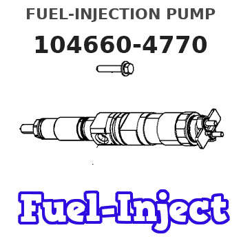
Information fuel-injection pump
BOSCH
9 461 620 062
9461620062
ZEXEL
104660-4770
1046604770
Rating:
Compare Prices: .
As an associate, we earn commssions on qualifying purchases through the links below

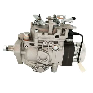
VE Fuel Injection Pump VE6/12F1800RND641 Compatible For Nissan TD42 Diesel Engine Diesel Fuel Injection VE Pump 104660-4770 104760-4781
VWUNFRES Fuel delivery: the fuel pump pumps the fuel out of the fuel tank through negative pressure or positive pressure, and delivers it to the fuel injection system or carburetor of the engine through the fuel pipeline. || Improve fuel efficiency, reduce fuel waste, improve vehicle fuel economy, ensure engine performance, prolong engine life, protect engine fuel system, reduce engine wear caused by fuel pollution, adapt to different working conditions, and get the best fuel supply under different working conditions. || Sealing design: use our sealed high-pressure fuel pump to enjoy long-term leak-free operation. Small size: Our high-pressure fuel pump has a compact design, ensuring easy installation and saving space. High precision: Experience accurate fuel delivery with our high-pressure fuel pump specially designed for high precision. || To maintain the fuel pressure, the fuel pump needs to maintain a certain fuel pressure to ensure that the fuel can smoothly enter the combustion chamber of the engine. This is especially important for modern electronic fuel injection system, because fuel injection needs accurate fuel pressure to ensure the accuracy of fuel injection quantity. || VE Fuel Injection Pump VE6/12F1800RND641 Compatible For Nissan TD42 Diesel Engine Diesel Fuel Injection VE Pump 104660-4770 104760-4781
VWUNFRES Fuel delivery: the fuel pump pumps the fuel out of the fuel tank through negative pressure or positive pressure, and delivers it to the fuel injection system or carburetor of the engine through the fuel pipeline. || Improve fuel efficiency, reduce fuel waste, improve vehicle fuel economy, ensure engine performance, prolong engine life, protect engine fuel system, reduce engine wear caused by fuel pollution, adapt to different working conditions, and get the best fuel supply under different working conditions. || Sealing design: use our sealed high-pressure fuel pump to enjoy long-term leak-free operation. Small size: Our high-pressure fuel pump has a compact design, ensuring easy installation and saving space. High precision: Experience accurate fuel delivery with our high-pressure fuel pump specially designed for high precision. || To maintain the fuel pressure, the fuel pump needs to maintain a certain fuel pressure to ensure that the fuel can smoothly enter the combustion chamber of the engine. This is especially important for modern electronic fuel injection system, because fuel injection needs accurate fuel pressure to ensure the accuracy of fuel injection quantity. || VE Fuel Injection Pump VE6/12F1800RND641 Compatible For Nissan TD42 Diesel Engine Diesel Fuel Injection VE Pump 104660-4770 104760-4781
You can express buy:
USD 388.94
13-05-2025
13-05-2025
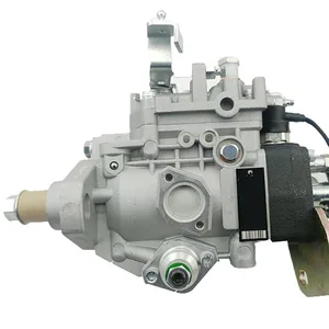
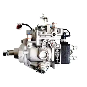
VE Fuel Injection Pump VE6/12F1800RND641 For Nissan TD42 Diesel Engine Diesel Fuel Injection VE Pump 104660-4770 104760-4781
USD 433.49
19-05-2025
19-05-2025
VE Fuel Injection Pump VE6/12F1800RND641 For Nissan TD42 Diesel Engine Diesel Fuel Injection VE Pump 104660-4770 104760-4781
USD 405.69
19-05-2025
19-05-2025
VE Fuel Injection Pump VE6/12F1800RND641 For Nissan TD42 Diesel Engine Diesel Fuel Injection VE Pump 104660-4770 104760-4781
Images:
USD 387.37

[02-May-2025]
Include in #2:
104760-4770
as FUEL INJECTION PUMP
Cross reference number
Zexel num
Bosch num
Firm num
Name
Information:
Start By:a. remove turbocharger 1. Install the turbocharger on Tool (A).2. Put alignment marks on the two housings and cartridge assembly of the turbocharger for correct alignment during assembly.3. Loosen clamp (3), and remove compressor housing (4) from cartridge assembly (2).4. Loosen the remaining clamp, and remove cartridge assembly (2) from turbine housing (1).
Typical Example5. Put the cartridge group (shown in the illustration) with nut (16) up in Tool (B). Use a 5S9566 Sliding T-Wrench and a universal socket to remove nut (16) that holds the compressor wheel (15) to the wheel assembly (19).6. Remove compressor wheel (15) and housing assembly (6) from wheel assembly (19). Remove piston ring (13) from the wheel assembly.7. Use Tool (C), and remove snap ring (5) from housing assembly (6). Remove insert (14) and sleeve (18) from the housing assembly. Remove seal (22) from insert (14). Remove ring (20) from sleeve (18).8. Remove oil deflector (23), thrust ring (21), bearing assembly (7), spacer sleeve (24) and thrust ring (8) from housing assembly (6).9. Use Tool (D), and remove snap ring (9) from the housing assembly. Remove bearing (25). Remove snap ring (10) with Tool (D).10. Use Tool (D), and remove snap ring (12) from the housing assembly. Remove bearing (26). Remove snap ring (11) with Tool (D).11. Check all the parts of the turbocharger for damage. If any parts are damaged, use new parts for replacement. See Special Instruction Form No. SMHS6854 for turbocharger reconditioning. Also, see Guidelines For Reusable Parts, Form No. SEBF8018. The following steps are for assembly of the turbocharger.12. Make sure that all the oil passages in the turbocharger cartridge housing are clean and free of dirt and foreign material. Do not put oil on any parts of the turbocharger until after the compressor wheel has been installed. After the turbocharger has been assembled, put clean engine oil into the oil inlet of the turbocharger.
Make sure the snap rings that hold bearings (25) and (26) in housing assembly (6) are installed with the round edge of the outside diameter toward the bearing.
13. Install snap ring (11) with Tool (D). Install bearing (26). Install snap ring (12) with Tool (D).14. Install snap ring (10) with Tool (D). Install bearing (25). Install snap ring (9) with Tool (D).15. Put wheel assembly (19) in position on Tool (B) with the threaded portion end up. Put 6V2055 High Vacuum Grease in the groove for piston ring (13) at assembly to one half or more of the depth of the groove all the way around.16. Install piston ring (13) in the groove in wheel assembly (19).17. Put housing assembly (6) in position on wheel assembly (19).18. Install thrust ring (8) and spacer sleeve (24) on wheel assembly (19).19. Make sure the screen is in place in bearing assembly (7). Install bearing assembly (7) over spacer sleeve (24). Make sure the screen in the bearing assembly is facing toward housing assembly (6) when it is installed.20. Install thrust ring (21) and oil deflector (23)