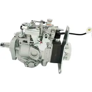
Information fuel-injection pump
BOSCH
9 461 620 910
9461620910
ZEXEL
104649-5250
1046495250

Rating:
Compare Prices: .
As an associate, we earn commssions on qualifying purchases through the links below

Fuel Injection Pump 104649-5250 for Isuzu Engine C240 TCM Forklift 6000 LB
FGNTWP Part Number:104649-5250, 1046495250, 9 461 620 910, 9461620910 || Applications:Fit for TCM Forklift: 6000 LB
FGNTWP Part Number:104649-5250, 1046495250, 9 461 620 910, 9461620910 || Applications:Fit for TCM Forklift: 6000 LB

ZGZJYBL Fuel Injection Pump for Isuzu C240 Engine for TCM 6000 LB Forklift 104649-5250 1046495250
ZGZJYBL Item Name:Fuel Injection Pump || Item Number:104649-5250, 1046495250, 9 461 620 910, 9461620910 || Application: Fit for TCM Forklift: 6000 LB Fit for Isuzu Engine: C240 || Attention: If you are unsure if the product is suitable for your machine model. In order not to delay your use of the parts, please provide your engine nameplate or serial number and part number, and we will help you confirm if it is suitable. To avoid unnecessary returns, please carefully check the product image and part number to ensure that it is the product you want. || Tip: If you need any other parts, please contact us - we are a professional sales team and have many products to offer to you. Many buyers are very satisfied with our service. You can get first-class products and high-quality services from us, believe me, you will have a pleasant shopping experience here.
ZGZJYBL Item Name:Fuel Injection Pump || Item Number:104649-5250, 1046495250, 9 461 620 910, 9461620910 || Application: Fit for TCM Forklift: 6000 LB Fit for Isuzu Engine: C240 || Attention: If you are unsure if the product is suitable for your machine model. In order not to delay your use of the parts, please provide your engine nameplate or serial number and part number, and we will help you confirm if it is suitable. To avoid unnecessary returns, please carefully check the product image and part number to ensure that it is the product you want. || Tip: If you need any other parts, please contact us - we are a professional sales team and have many products to offer to you. Many buyers are very satisfied with our service. You can get first-class products and high-quality services from us, believe me, you will have a pleasant shopping experience here.

You can express buy:
USD 406.7
19-05-2025
19-05-2025
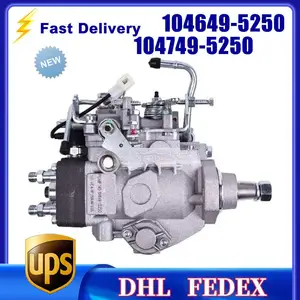
Fuel Injection VE Pump NP-VE4/9F1250LNP1035 High Quality 104749-5250 104649-5250 8970487570 For C240 ISUZU
USD 517.63
14-06-2025
14-06-2025
104649-5250 NEW FUEL INJECTION PUMP 104749-5250 8970487570 VE4/9F1250LNP1035 for ISUZU C240
USD 393.14
13-05-2025
13-05-2025
Diesel Fuel Injection VE Pump 104649-5250 104749-5250 8970487570 NP-VE4/9F1250LNP1035 For ISUZU
Images:
USD 430.42

[14-Jun-2025]
Include in #2:
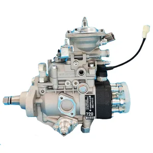
104749-5250
as FUEL INJECTION PUMP
Cross reference number
Zexel num
Bosch num
Firm num
Name
104649-5250
FUEL-INJECTION PUMP
Q 11CJ FUEL INJECTION PUMP VE4 VE
Q 11CJ FUEL INJECTION PUMP VE4 VE
Information:
Camshaft
When reconditioning an engine, check the diameter of the camshaft bearing journals and the camshaft lobe height.Camshaft bearing journals have a diameter of 2.5000 .0005 in. (63.500 0.013 mm) and the minimum diameter worn is 2.4970 in. (63.424 mm).To find lobe lift (A) of camshaft, use the following procedure:1. Measure lobe height (B) of one exhaust and one intake lobe.2. Measure base circle (C) of one exhaust and one intake lobe.3. Subtract base circle (C) dimension (STEP 2) from lobe height (B) dimension (STEP 1). The difference is actual lobe lift (A).4. The specified (new) lobe lift (A) is: (a) Exhaust lobe ... .3071 in.(7.800 mm)(b) Intake lobe ... .3077 in.(7.816 mm)5. The maximum permissible difference between actual lobe lift (STEP 3) and specified lobe lift (STEP 4) is .025 in. (0.64 mm).
CAMSHAFT LOBE
A. Lobe lift. B. Lobe height. C. Base circle.With camshaft installed in the cylinder block, check end play. End play with new components should be .007 .003 in. (0.18 0.08 mm). The maximum permissible end play is .020 in. (0.51 mm).Camshaft Followers
Use an 8S2293 Magnet to remove the cam followers.
REMOVING CAM FOLLOWERSCam followers establish a wear pattern with the camshaft lobes. Identify and reinstall the followers removed. Dishing or circular wear pattern is allowed on the cam follower face, providing the wear face keeps a polished appearance. Replace the follower if the wear face is rough or shows signs of scuffing. A new follower can be used with an old camshaft, providing the lobe is in good condition. Put engine oil on the cam followers and the camshaft lobes before installing the cam followers. Use new cam followers with a new camshaft.Camshaft Gears
1. Remove screw (1) and washer (2) from end of camshaft.
REMOVING TIMING ADVANCE RETAINING SCREW
1. Screw. 2. Washer.2. Remove timing advance unit from the camshaft.3. Install puller (A), with spacer (C) over the shaft in the camshaft spacer (B) on spacer (C) as shown and remove the gear from the camshaft.
REMOVING GEAR (Typical Example)
A. 1P2321 Puller. B. 8S5579 Spacer. C. 9S9155 Spacer.To install the gear use the following procedure:1. Heat the gear to a temperature of approximately 400°F (204°C) before installing on the camshaft.
Do not heat the gear with a torch. Do not heat the gear to a temperature of more than 600°F (315°C). Heating the gear with a torch or to a temperature of more than 600°F (315°C) may cause the two drive dowels for the automatic timing advance to loosen and come out of the gear.
2. Align slot in gear hub with the pin in the camshaft. Install the gear on the camshaft with timing mark on gear aligned with timing mark on crankshaft gear. Be sure the gear is completly seated against the shoulder of the camshaft.
Do not drive the gear on the camshaft.
3. Align holes in weights with dowels in gear and install the automatic timing advance.4. Align pin (3) in washer with hole (4) in camshaft and install washer (2).5. Install screw (1) and