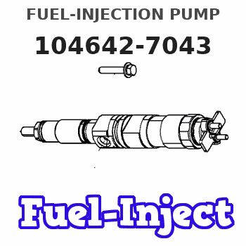
Information fuel-injection pump
BOSCH
9 461 615 049
9461615049
ZEXEL
104642-7043
1046427043
Rating:
Compare Prices: .
As an associate, we earn commssions on qualifying purchases through the links below

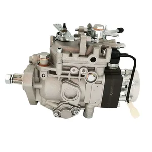
YRGGHUI Construction Machinery Parts 104642-7043 OEM Fuel Injection Pump Assy
YRGGHUI OEM NO. : 104642-7043 || Types of automotive components: fuel pump, diesel pump, high-pressure fuel pump component, fuel pump component || Fuel pump: can enhance power, reduce fuel consumption, provide strong power, smooth acceleration, and ensure the stability of the fuel pump at high temperatures. Make your car full of power || Before purchasing the fuel pump, please confirm if the picture and OEM number match your part! This is really important! If they are not the same component, they cannot be used! All products will undergo testing before shipment!! || If you have any questions, please feel free to contact us and we will reply within 24 hours. Please confirm the product based on your vehicle model, year, code, and tag number. thank you. Automotive parts have accurate OEM numbers. Please ensure that the OEM number is suitable for your car
YRGGHUI OEM NO. : 104642-7043 || Types of automotive components: fuel pump, diesel pump, high-pressure fuel pump component, fuel pump component || Fuel pump: can enhance power, reduce fuel consumption, provide strong power, smooth acceleration, and ensure the stability of the fuel pump at high temperatures. Make your car full of power || Before purchasing the fuel pump, please confirm if the picture and OEM number match your part! This is really important! If they are not the same component, they cannot be used! All products will undergo testing before shipment!! || If you have any questions, please feel free to contact us and we will reply within 24 hours. Please confirm the product based on your vehicle model, year, code, and tag number. thank you. Automotive parts have accurate OEM numbers. Please ensure that the OEM number is suitable for your car
You can express buy:
USD 388.94
13-05-2025
13-05-2025
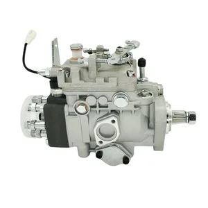
Construction machinery parts 104642-7043 high quality OEM Fuel Injection Pump Assy hot selling
USD 406.7
13-05-2025
13-05-2025
Construction machinery parts 104642-7043 high quality OEM Fuel Injection Pump Assy hot selling
USD 409.65
13-05-2025
13-05-2025
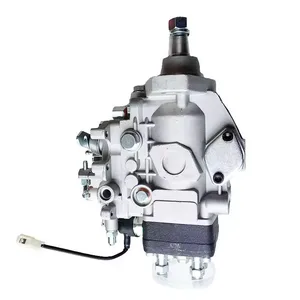
Construction machinery parts 104642-7043 high quality OEM Fuel Injection Pump Assy hot selling
Images:
USD 382.51

[15-May-2025]
USD 398.16

[29-May-2025]
Include in #2:
104742-7043
as FUEL INJECTION PUMP
Cross reference number
Zexel num
Bosch num
Firm num
Name
Information:
Image1.1.1
Image1.1.2
Image1.1.3
Image1.1.4
Image1.1.5
Image1.1.6
Image1.1.7
Image1.1.8
Image1.1.9
PROCEDURES FOR DPF MODULE REWORK
PROCEDURE ( A ) See Image 1.2.1
Butt weld ring flush to retainer ring on the inlet assembly in 4 spots.
Fillet weld (3 mm weld size) 4 tabs (at 0, 90,180 and 270 degrees.
PROCEDURE ( B ) See Image 1.2.2
Butt weld ring flush to retainer ring on the inlet assembly in 4 spots.
Fillet weld (3 mm weld size) 4 tabs (at 0, 90,180 and 270 degrees.
PROCEDURE ( C ) See Image 1.2.3
Butt weld ring flush to retainer ring on the inlet assembly in 4 spots.
Fillet weld (3 mm weld size) 4 tabs (at 0, 90,180 and 270 degrees.
PROCEDURE ( D ) See Image 1.2.4
Butt weld ring flush to retainer ring on the inlet assembly in 4 spots.
Fillet weld (3 mm weld size) 4 tabs (at 0, 90,180 and 270 degrees.
PROCEDURE ( E ) See Image 1.2.5
Butt weld ring flush to retainer ring on inlet assembly in 4 spots.
Fillet weld 2 pins (at 0 and 180 degree orientation) to outlet side of DPF's 300 mm from each other.
Drill 5/8" holes in the outlet assembly flanges 300 mm from each other.
Place tube flush to the flange inside this hole and weld to outlet assembly.
PROCEDURE ( F ) See Image 1.2.6
Position plates (at 0 and 180 degree orientation) to outlet side of the DPF flange.
Allow plates to extend ( minimum 1/4 inch ) past outer edge. Using slots in plates
weld into place.
PROCEDURE ( G ) See Image 1.2.7
Fillet weld (3 mm weld size) 2 pins (at 0 and 180 degree orientation) to outlet side of DPF 260 mm from each other.
Drill a 5/8" hole in the outlet assembly flange 260 mm from each other 13 mm deep.
Place tube flush to the flange inside this hole and weld to outlet assembly.
PROCEDURE ( H ) See Image 1.2.8
Fillet weld 2 pins (at 0 and 180 degree orientation) to outlet side of both DPF's 300 mm from each other.
Drill 5/8" holes in the outlet assembly flanges 300 mm from each other 13 mm deep.
Place tubes flush to the flange inside this hole and weld to outlet assembly.
PROCEDURE ( I ) See Image 1.2.9 and Image 1.2.10
Remove the clamp and gasket from DPF inlet side.
Mate inlet flange to DPF without gasket or clamp.
Tack weld in place.
Apply a continuous weld to the inlet flange/DPF seam.
Image1.2.1
Image1.2.2
Image1.2.3
Image1.2.4
Image1.2.5
Image1.2.6
Image1.2.7
Image1.2.8
Image1.2.9
Image1.2.10
Filter Module Cross Reference Guide See Image 1.3.1.
Image1.3.1