Information fuel-injection pump
BOSCH
9 461 619 356
9461619356
ZEXEL
104642-1451
1046421451

Rating:
Compare Prices: .
As an associate, we earn commssions on qualifying purchases through the links below

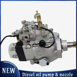
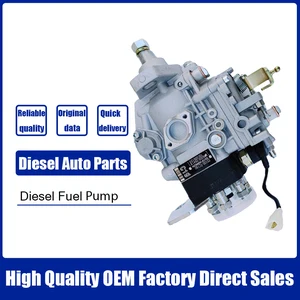
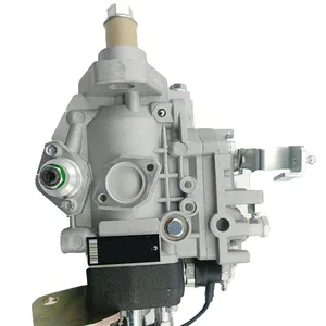
Fuel Injection Pump 9461619356 104642-1451 for Isuzu Engine 4JB1
FGNTWP Part Number:1046421451, 104642-1451, 9 461 619 356, 9461619356 || Applications:for Isuzu Engine 4JB1
FGNTWP Part Number:1046421451, 104642-1451, 9 461 619 356, 9461619356 || Applications:for Isuzu Engine 4JB1

Aftermarket Fuel Injection Pump 9461619356 104642-1451 Fit Intended For Engine 4JB1
Generic Motorcycle Parts || Heavy Equipment Parts || Spare Parts || Fuel Systems
Generic Motorcycle Parts || Heavy Equipment Parts || Spare Parts || Fuel Systems

You can express buy:
USD 653.93
14-06-2025
14-06-2025
4JB1 Diesel Fuel Injection Pump 104642-1451 NP-VE4/12F1800LNP1491 897120 1791 For 4JB1 Isuzu
USD 419.7
14-06-2025
14-06-2025
Diesel Fuel Injection Pump 104642-1451 VE4/12F1800LNP1491 8971201791 For ISUZU
USD 442.99
19-05-2025
19-05-2025
4JB1 Diesel Fuel Injection Pump 104642-1451 NP-VE4/12F1800LNP1491 897120 1791 For 4JB1 Isu-zu
Images:
USD 411.32

[13-May-2025]
USD 393.14

[13-May-2025]
USD 411.32
[13-May-2025]
USD 388.94

[13-May-2025]
Cross reference number
Zexel num
Bosch num
Firm num
Name
104642-1451
FUEL-INJECTION PUMP
Q 11CJ FUEL INJECTION PUMP VE4 VE
Q 11CJ FUEL INJECTION PUMP VE4 VE
Information:
Start By:a. remove rocker arm assemblies and push rods1. Disconnect the governor control linkage. See the 3114 & 3116 Engines Governor Service Manual, Form No. SENR6454.
Do not move the fuel control linkage or the injector racks with out the Injector Compressors [Tool (A)] installed. Damage to the fuel injectors can result. After installation of Tool (A), tap on the top of each fuel injector lightly with a rubber mallet to prevent any binding or side loading in the fuel injectors.
2. When removing the fuel control linkage with the fuel injectors in place, install Tool (A) on the fuel injectors, and slightly compress the injector springs.3. Remove four bolts (1) and fuel control linkage (2). The following steps are for the installation of the fuel control linkage.4. Be sure the two screws in each inboard bracket are loose.5. Put fuel control linkage in position on the cylinder head assembly. Be sure all injector racks are engaged and the small dowel in each mounting bracket is in the proper position before tightening bolts (1). Install four bolts (1), and tighten them as follows: a. Tighten the two outer bearing bracket mounting bolts.b. Tighten the inner bearing bracket(s) mounting bolt(s).c. Position the inner bearing(s) to allow free rotation of the rack control rod.d. Tighten the two screws in on each inner bracket(s) to a torque of 3.5 0.2 N m (31 2 lb in).e. The control rod must rotate when a force of 4.4 N (1 lb) or less is applied to control lever (3) in the direction indicated by arrows.6. Connect the governor control linkage. See the 3114 & 3116 Engines Governor Service Manual, Form No. SENR6454.7. After installation of the rocker arm assemblies and push rods, Check and/or adjust the following: Injector Synchronization, Fuel Setting, Fuel Timing, Valve Lash. See the 3114 & 3116 Diesel Truck Engines Systems Operation Testing & Adjusting module, Form No. SENR6437 to check and/or adjust the above items.End By:a. install rocker arm assemblies and push rods