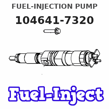
Information fuel-injection pump
BOSCH
9 461 628 036
9461628036
ZEXEL
104641-7320
1046417320
Rating:
Compare Prices: .
As an associate, we earn commssions on qualifying purchases through the links below

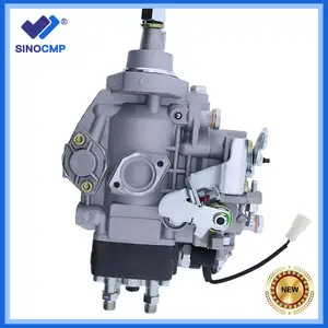
Fuel Injection Pump Compatible For Cummins Engine B3.3 QSB3.3 104741-7320 1047417320 104641-7320 1046417320 Engine Replacement Parts
TBEFQVAW Lightweight design: effectively reduces vehicle load, improves fuel economy, and facilitates installation and handling || Multi specification adaptation: providing multiple flow specifications and models to meet the needs of different displacement engines || Adaptive installation: Standardized interface design, compatible with 95% of mainstream engine models, no need for complex modifications || Anti corrosion coating: The surface of key components is covered with anti-corrosion coating, which is not afraid of humid coastal environments and harsh weather conditions || Fuel Injection Pump Compatible For Cummins Engine B3.3 QSB3.3 104741-7320 1047417320 104641-7320 1046417320 Engine Replacement Parts
TBEFQVAW Lightweight design: effectively reduces vehicle load, improves fuel economy, and facilitates installation and handling || Multi specification adaptation: providing multiple flow specifications and models to meet the needs of different displacement engines || Adaptive installation: Standardized interface design, compatible with 95% of mainstream engine models, no need for complex modifications || Anti corrosion coating: The surface of key components is covered with anti-corrosion coating, which is not afraid of humid coastal environments and harsh weather conditions || Fuel Injection Pump Compatible For Cummins Engine B3.3 QSB3.3 104741-7320 1047417320 104641-7320 1046417320 Engine Replacement Parts

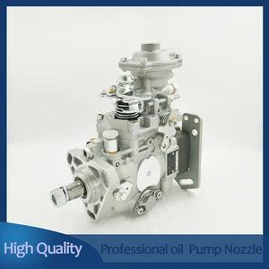
Nayuank Fuel Injection Pump 6205711370 104741-7320 1046417320 Fits For Cummins Engine B3.3 QSB3.3
Nayuank Part Name: Fuel Injection Pump || Part Number: 6205711370 104741-7320 Note: Please check the fitment carefully before purchase. Or just tell us the part number you need. || Engine Model: QSB3.3 || Applicable: Fits For Cummins Engine B3.3 QSB3.3 || Package included: 1pcs Fuel Injection Pump 6205711370 104741-7320 1046417320
Nayuank Part Name: Fuel Injection Pump || Part Number: 6205711370 104741-7320 Note: Please check the fitment carefully before purchase. Or just tell us the part number you need. || Engine Model: QSB3.3 || Applicable: Fits For Cummins Engine B3.3 QSB3.3 || Package included: 1pcs Fuel Injection Pump 6205711370 104741-7320 1046417320

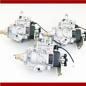
VIIKEND Fuel Injection Pump 6205711370 104741-7320 1046417320 Compatible with Cummins Engine B3.3 QSB3.3
VIIKEND Part Name: Fuel Injection Pump || Part Number: 6205711370 104741-7320 Note: Please check the fitment carefully before purchase. Or just tell us the part number you need. || Engine Model: QSB3.3 || Applicable: Compatible with Cummins Engine B3.3 QSB3.3 || Package included: 1pcs Fuel Injection Pump 6205711370 104741-7320 1046417320
VIIKEND Part Name: Fuel Injection Pump || Part Number: 6205711370 104741-7320 Note: Please check the fitment carefully before purchase. Or just tell us the part number you need. || Engine Model: QSB3.3 || Applicable: Compatible with Cummins Engine B3.3 QSB3.3 || Package included: 1pcs Fuel Injection Pump 6205711370 104741-7320 1046417320
You can express buy:
USD 619.97
29-06-2025
29-06-2025
New Fuel Pump For 4D95 Excavator 4989125 4989454 104641-7320 6205-71-1370
USD 450
14-06-2025
14-06-2025
Automotive Parts Diesel Engine Fuel Pump Fuel Injection Pump New VE Fuel Pump Assembly 104641-7320
USD 398.7
14-06-2025
14-06-2025
104641-7320 6205711380 Engine Parts Diesel Fuel Injection Pump For Truck Engine Excavator
Images:
USD 653.93

[19-May-2025]
USD 492

[19-May-2025]
USD 406.7

[19-May-2025]
Include in #2:
104741-7320
as FUEL INJECTION PUMP
Cross reference number
Zexel num
Bosch num
Firm num
Name
Information:
Start By:a. remove valve covers 1. Loosen the fuel injection line nut at the nozzle end with tool (A).2. Loosen the fuel line nut at the fuel injection line adapter with tool (B). Remove inner fuel injection lines (1). Install caps and plugs on all fuel line openings to keep dirt out of the fuel system. If necessary, use tooling (D) to turn the engine so the valves do not make contact with the pistons when the valves are opened with tool (C) to remove the push rods.3. Put compression on the valve springs with tool (C), and remove push rods (2). Put identification marks on the push rods as to their location in the engine.4. Push the push rod end of the rocker arms down. 5. Remove the intake valve lifter with tooling (E) as follows:a. Install 5P2685 Nut (3) and 5P6601 Collet (4) on 5P2408 Outer Handle Assembly (5).b. Install 5P6599 Inner Handle Assembly (6) in 5P2408 Outer Handle Assembly (5). c. Install tooling (E) in the intake valve lifter. Hold the 5P2408 Outer Handle Assembly, and tighten the 5P6599 Inner Handle Assembly until the 5P6601 Collet is tight against the inside of the intake valve lifter. d. Remove intake valve lifters (7) from the cylinder block with tooling (E). Put identification marks on the lifters as to their location in the engine. 6. Remove the exhaust valve lifters with tooling (E) as follows:a. Install 5P2685 Nut (3) and 5P6601 Collet (4) on 5P2408 Outer Handle Assembly (5). The opening in the cylinder head assembly for the intake valve lifter is larger than the opening in the exhaust valve lifter side. The tooling and each valve lifter must be installed and removed from the intake valve lifter side.b. Install the outer handle assembly in the intake valve lifter side of the cylinder head assembly. Slide the flat area of 5P2408 Outer Handle Assembly (5) through the head casting, and install the 5P6601 Collet in the exhaust valve lifters. c. Install 5P6599 Inner Handle Assembly (6) in 5P2408 Outer Handle Assembly (5). Hold the 5P2408 Handle Assembly, and tighten the 5P6599 Handle Assembly until the 5P6601 Collet is tight against the inside of the exhaust valve lifter.d. Pull the exhaust valve lifter up until the spring on the exhaust valve lifter is free from the cylinder block.e. Remove the 5P6599 Inner Handle Assembly. Slide the 5P2408 Outer Handle Assembly through the head casting, and remove it from the intake valve lifter side of the cylinder head. f. Use a magnet, and remove exhaust valve lifters (8) from the intake valve lifter side of the cylinder head assembly. Put identification marks on the lifters as to their location in the engine.7. Remove the guide springs from the lifters.Install Valve Lifters
Steps 1 and 2 must be done to install intake or exhaust valve lifters.
Make sure guide spring (9) is not damaged or worn. If the guide spring is damaged or worn, replace the guide spring. See Guideline For Reusable
Steps 1 and 2 must be done to install intake or exhaust valve lifters.
Make sure guide spring (9) is not damaged or worn. If the guide spring is damaged or worn, replace the guide spring. See Guideline For Reusable