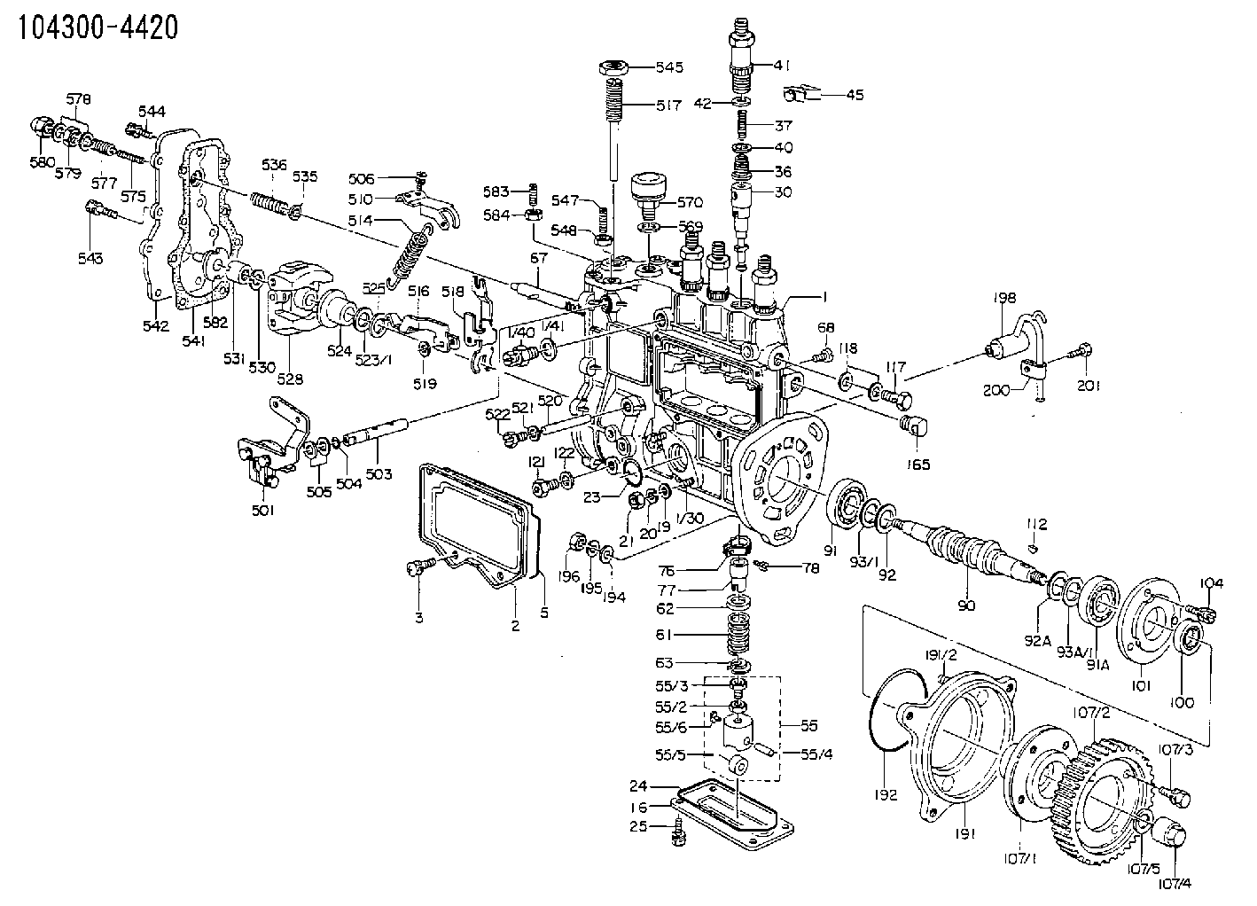
Information fuel-injection pump
BOSCH
9 410 612 823
9410612823
ZEXEL
104300-4420
1043004420
ISUZU
8941730470
8941730470

Rating:
Scheme ###:
| 1. | [1] | 130070-1020 | PUMP HOUSING |
| 1/30. | [2] | 029040-6320 | STUD |
| 1/40. | [1] | 131420-0420 | BLEEDER SCREW |
| 1/41. | [1] | 026512-1540 | GASKET D15.4&12.2T1.50 |
| 2. | [1] | 130010-1100 | COVER |
| 3. | [4] | 029050-5040 | FLAT-HEAD SCREW M5P0.8L9 |
| 5. | [1] | 130042-0500 | SEAL RING |
| 16. | [1] | 130010-1200 | COVER |
| 19. | [2] | 029300-6030 | PLAIN WASHER D11&6.4T0.5 |
| 20. | [2] | 014110-6440 | LOCKING WASHER |
| 21. | [2] | 013020-6040 | UNION NUT M6P1H5 |
| 23. | [1] | 130041-0200 | O-RING |
| 24. | [1] | 130042-0600 | SEAL RING |
| 25. | [4] | 029050-5040 | FLAT-HEAD SCREW M5P0.8L9 |
| 30. | [4] | 130101-4520 | PLUNGER-AND-BARREL ASSY |
| 36. | [4] | 130110-0320 | DELIVERY-VALVE ASSEMBLY |
| 37. | [4] | 131112-0600 | COILED SPRING |
| 40. | [4] | 130115-0000 | GASKET |
| 41. | [4] | 130116-0520 | FITTING |
| 42. | [4] | 131117-3200 | SLOTTED WASHER |
| 45. | [2] | 130122-0420 | PLATE |
| 55. | [4] | 130200-0220 | TAPPET |
| 55/2. | [1] | 130201-0000 | UNION NUT |
| 55/3. | [1] | 130202-0100 | HEXAGON SCREW |
| 55/4. | [1] | 130203-0100 | BEARING PIN |
| 55/5. | [1] | 152112-0100 | ROLLER |
| 55/6. | [1] | 130206-0000 | SLIDER |
| 61. | [4] | 130215-0000 | COMPRESSION SPRING |
| 62. | [4] | 130216-0000 | SLOTTED WASHER |
| 63. | [4] | 130217-0000 | SLOTTED WASHER |
| 67. | [1] | 130223-1220 | CONTROL RACK |
| 68. | [1] | 131226-0300 | FLAT-HEAD SCREW |
| 76. | [4] | 130240-0100 | PINION |
| 77. | [4] | 130241-0100 | CONTROL SLEEVE |
| 78. | [4] | 131242-0100 | FLAT-HEAD SCREW |
| 90. | [1] | 130300-2100 | CAMSHAFT |
| 91. | [1] | 028001-7010 | BEARING PLATE |
| 91A. | [1] | 016630-2640 | BEARING PLATE |
| 92. | [1] | 130302-0100 | SPACER RING |
| 92A. | [1] | 130302-0200 | SPACER RING |
| 93/1. | [0] | 029311-7010 | SHIM D22&17T0.1 |
| 93/1. | [0] | 029311-7020 | SHIM D22&17T0.12 |
| 93/1. | [0] | 029311-7030 | SHIM D22&17T0.14 |
| 93/1. | [0] | 029311-7040 | SHIM D22&17T0.16 |
| 93/1. | [0] | 029311-7050 | SHIM D22&17T0.18 |
| 93/1. | [0] | 029311-7060 | SHIM D22&17T0.5 |
| 93/1. | [0] | 029311-7070 | SHIM D22&17T1.0 |
| 93/1. | [0] | 029311-7090 | SHIM D22&17T0.3 |
| 93/1. | [0] | 029311-7210 | SHIM D22&17T0.7 |
| 93/1. | [0] | 029311-7220 | SHIM D22&17T1.4 |
| 93/1. | [0] | 139417-0000 | SHIM D22&17T2.4 |
| 93A/1. | [0] | 029311-7010 | SHIM D22&17T0.1 |
| 93A/1. | [0] | 029311-7020 | SHIM D22&17T0.12 |
| 93A/1. | [0] | 029311-7030 | SHIM D22&17T0.14 |
| 93A/1. | [0] | 029311-7040 | SHIM D22&17T0.16 |
| 93A/1. | [0] | 029311-7050 | SHIM D22&17T0.18 |
| 93A/1. | [0] | 029311-7060 | SHIM D22&17T0.5 |
| 93A/1. | [0] | 029311-7070 | SHIM D22&17T1.0 |
| 93A/1. | [0] | 029311-7090 | SHIM D22&17T0.3 |
| 93A/1. | [0] | 029311-7210 | SHIM D22&17T0.7 |
| 93A/1. | [0] | 029311-7220 | SHIM D22&17T1.4 |
| 93A/1. | [0] | 139417-0000 | SHIM D22&17T2.4 |
| 100. | [1] | 029621-7020 | PACKING RING |
| 101. | [1] | 130316-0500 | COVER |
| 104. | [3] | 020006-1440 | BLEEDER SCREW M6P1L14 |
| 107. | [1] | 156636-0420 | COUPLING PLATE |
| 107/1. | [1] | 156635-9500 | COUPLING PLATE |
| 107/2. | [1] | 156211-8600 | TOOTHED GEAR |
| 107/3. | [4] | 020018-2270 | BLEEDER SCREW M8P1.25L22 7T |
| 107/4. | [1] | 131325-2700 | UNION NUT |
| 107/5. | [1] | 014111-2420 | LOCKING WASHER |
| 112. | [1] | 025803-1610 | WOODRUFF KEY |
| 117. | [1] | 139812-0900 | EYE BOLT |
| 118. | [2] | 029341-2080 | GASKET |
| 121. | [2] | 029010-6010 | CAPSULE M6P1.0L7 |
| 122. | [2] | 026506-1040 | GASKET D9.9&6.2T1 |
| 165. | [1] | 130448-0400 | CAP |
| 191. | [1] | 130459-0720 | BRACKET |
| 191/2. | [3] | 029040-8600 | STUD |
| 192. | [1] | 029637-5040 | O-RING |
| 194. | [3] | 014010-8140 | PLAIN WASHER D18&8.5T1.6 |
| 195. | [3] | 014110-8440 | LOCKING WASHER |
| 196. | [3] | 013020-8040 | UNION NUT M8P1.25H7 |
| 198. | [1] | 130431-1320 | PIPE |
| 200. | [1] | 130447-0200 | CLAMPING BAND |
| 201. | [1] | 020006-1240 | BLEEDER SCREW M6P1L12 4T |
| 501. | [1] | 130531-2320 | CONTROL LEVER |
| 503. | [1] | 154324-1900 | LEVER SHAFT |
| 504. | [1] | 029630-8080 | O-RING |
| 505. | [0] | 029311-1070 | SHIM D16&11T0.5 |
| 505B. | [0] | 029311-1090 | SHIM D16&11T0.3 |
| 505C. | [0] | 029311-1020 | PLAIN WASHER D16&11T1 |
| 506. | [2] | 029050-5040 | FLAT-HEAD SCREW M5P0.8L9 |
| 510. | [1] | 130524-0300 | SWIVELLING LEVER |
| 514. | [1] | 130510-0600 | GOVERNOR SPRING |
| 516. | [1] | 130520-0300 | TENSIONING LEVER |
| 517. | [1] | 154031-2800 | FLAT-HEAD SCREW |
| 518. | [1] | 130522-0400 | GUIDE LEVER |
| 519. | [1] | 130523-0100 | SPACER BUSHING |
| 520. | [1] | 130523-0500 | BEARING PIN |
| 521. | [2] | 026510-1340 | GASKET D13.4&10.2T1 |
| 522. | [2] | 029111-0190 | CAPSULE |
| 523/1. | [0] | 029311-2040 | SHIM D22&12.5T0.1 |
| 523/1. | [0] | 029311-2050 | SHIM D22&12.5T0.2 |
| 523/1. | [0] | 029311-2060 | SHIM D22&12.5T0.5 |
| 523/1. | [0] | 029311-2070 | SHIM D22&12.5T1 |
| 523/1. | [0] | 029311-2130 | SHIM D22&12.5T0.6 |
| 523/1. | [0] | 029311-2140 | SHIM D22&12.5T0.7 |
| 523/1. | [0] | 029311-2150 | SHIM D22&12.5T0.8 |
| 523/1. | [0] | 029311-2160 | SHIM D22&12.5T0.9 |
| 524. | [1] | 130501-0200 | SLIDING PIECE |
| 525. | [1] | 130523-0800 | BUSHING |
| 528. | [1] | 130500-0620 | FLYWEIGHT ASSEMBLY |
| 530. | [1] | 014110-8440 | LOCKING WASHER |
| 531. | [1] | 029230-8000 | UNION NUT |
| 535. | [1] | 154325-0800 | SLOTTED WASHER |
| 536. | [1] | 154171-5200 | COILED SPRING |
| 541. | [1] | 154350-7600 | GASKET |
| 542. | [1] | 130540-1020 | COVER |
| 543. | [7] | 020006-1840 | BLEEDER SCREW M6P1L18 |
| 544. | [1] | 029020-6240 | BLEEDER SCREW |
| 545. | [1] | 154011-0800 | HEXAGON NUT |
| 547. | [1] | 130532-0500 | FLAT-HEAD SCREW |
| 548. | [1] | 029240-6010 | UNION NUT M6P1.0H5* |
| 569. | [1] | 026512-1540 | GASKET D15.4&12.2T1.50 |
| 570. | [1] | 155406-0120 | AIR FILTER |
| 575. | [1] | 130511-1600 | COILED SPRING |
| 577. | [1] | 130514-0020 | GUIDE SLEEVE |
| 578. | [2] | 029331-2090 | GASKET D17&12.5T1 |
| 579. | [1] | 029201-2030 | UNION NUT M12P1.0H4 |
| 580. | [1] | 154159-0100 | CAP NUT |
| 582. | [1] | 154316-6420 | LEVER SHAFT |
| 583. | [1] | 130532-0500 | FLAT-HEAD SCREW |
| 584. | [1] | 029240-6010 | UNION NUT M6P1.0H5* |
Include in #1:
104304-4270
as FUEL INJECTION PUMP
Cross reference number
Zexel num
Bosch num
Firm num
Name
Information:
Assemble Governor
*Pump and Governor Reconditioning Tool Group1. Put the fuel injection pump housing in position on Tool (A). Install race (3), bearing (2) and race (1) on the end of the camshaft in the fuel injection pump housing. 2. Put flyweights (5) in position on carrier assembly (4), and install dowels (6) to hold the flyweights in place. The flyweights must move freely on the dowels and have 0.010 to 0.230 mm (.0004 to .0090 in) end play. 3. Install governor shaft (7) on carrier assembly (4). 4. Install dowel (8) in governor shaft (7), and slide carrier assembly (4) down on the governor shaft until dowel (8) fits into the slot in the carrier assembly.5. Install carrier assembly (4) on the end of the camshaft. 6. Install race (12), bearing (11), race (10) and ring (9) on riser (13). 7. Install riser (13) and spring (14), if equipped, on the governor shaft. 8. Install spool (18) and ring (19) on seat (17), and use Tool (B) to install ring (20) to hold them in position.9. Install seat (17) on spring (16) and spring (16) on shield (15). 10. Install dashpot assembly (21) on the governor shaft. 11. Install ring (22) in the groove on the governor shaft. Install sleeve (23), spring (25), the sleeve and bearing (24) on the governor shaft. 12. Use Tool (C) to hold spring (25) under compression, and install the ring in the groove on the governor shaft. 13. Install O-ring seal (26) on sleeve (27). Install piston (29) and sleeve (27) in the governor servo as shown.14. Install valve (28) in the governor servo as shown. 15. Install lockring (33) in the groove near the center of valve (28). Put sleeve (34), spring broken link spring (35) and seat (36) in position on valve (28), and install lockring (37) to hold them in place. 16. Put governor servo (30) in position on the fuel injection pump housing with piston (29) engaged over the rack. Make sure the lever is engaged in the slot groove of riser (13). 17. If dowel (43) was removed, install it in block (44) 31 0.5 mm (1.22 .02 in) above the outside surface of the block.18. Install bolt (45) in block (44) and spring (38) on bolt (45).19. Install stop screw (40) and the locknut on collar (42). Install power setting screw (41) and the locknut on the collar.20. Install collar (42) on bolt (45). Make an alignment of the hole in the collar with the notch in bolt (45), and install bolt (39). 21. If the dowels that align block (44) with the front governor housing were removed, install them 4.0 0.5 mm (.16 .02 in) above the outside surface of the front governor housing.22. Put block (44) in position on the front governor housing with the holes in the block in alignment with dowels in the front governor housing. 23. Install dowels (46) in the front governor housing 6.0 0.5
*Pump and Governor Reconditioning Tool Group1. Put the fuel injection pump housing in position on Tool (A). Install race (3), bearing (2) and race (1) on the end of the camshaft in the fuel injection pump housing. 2. Put flyweights (5) in position on carrier assembly (4), and install dowels (6) to hold the flyweights in place. The flyweights must move freely on the dowels and have 0.010 to 0.230 mm (.0004 to .0090 in) end play. 3. Install governor shaft (7) on carrier assembly (4). 4. Install dowel (8) in governor shaft (7), and slide carrier assembly (4) down on the governor shaft until dowel (8) fits into the slot in the carrier assembly.5. Install carrier assembly (4) on the end of the camshaft. 6. Install race (12), bearing (11), race (10) and ring (9) on riser (13). 7. Install riser (13) and spring (14), if equipped, on the governor shaft. 8. Install spool (18) and ring (19) on seat (17), and use Tool (B) to install ring (20) to hold them in position.9. Install seat (17) on spring (16) and spring (16) on shield (15). 10. Install dashpot assembly (21) on the governor shaft. 11. Install ring (22) in the groove on the governor shaft. Install sleeve (23), spring (25), the sleeve and bearing (24) on the governor shaft. 12. Use Tool (C) to hold spring (25) under compression, and install the ring in the groove on the governor shaft. 13. Install O-ring seal (26) on sleeve (27). Install piston (29) and sleeve (27) in the governor servo as shown.14. Install valve (28) in the governor servo as shown. 15. Install lockring (33) in the groove near the center of valve (28). Put sleeve (34), spring broken link spring (35) and seat (36) in position on valve (28), and install lockring (37) to hold them in place. 16. Put governor servo (30) in position on the fuel injection pump housing with piston (29) engaged over the rack. Make sure the lever is engaged in the slot groove of riser (13). 17. If dowel (43) was removed, install it in block (44) 31 0.5 mm (1.22 .02 in) above the outside surface of the block.18. Install bolt (45) in block (44) and spring (38) on bolt (45).19. Install stop screw (40) and the locknut on collar (42). Install power setting screw (41) and the locknut on the collar.20. Install collar (42) on bolt (45). Make an alignment of the hole in the collar with the notch in bolt (45), and install bolt (39). 21. If the dowels that align block (44) with the front governor housing were removed, install them 4.0 0.5 mm (.16 .02 in) above the outside surface of the front governor housing.22. Put block (44) in position on the front governor housing with the holes in the block in alignment with dowels in the front governor housing. 23. Install dowels (46) in the front governor housing 6.0 0.5