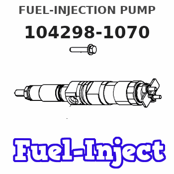
Information fuel-injection pump
BOSCH
9 410 618 367
9410618367
ZEXEL
104298-1070
1042981070
KUBOTA
1T07151012
1t07151012
Rating:
Compare Prices: .
As an associate, we earn commssions on qualifying purchases through the links below

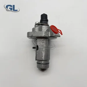
Fuel Pump 1T071-51012 104298-1070 9410618367, Compatible With Kubota RT140 Engine(104298-1070)
Adfghjk Precise Fit] 1T071-51012 Fuel Pump Assembly, Compatible with Kubota RT140 Excavator Engine (Model V3800-CR-TE4), perfect replacement for 104298-1070/9410618367 faulty parts. || <500ppm, working pressure up to 200PSI, life expectancy 300% longer than ordinary pumps. || Extreme working condition verification] Passed MIL-STD-810G vibration test (simulated 8,000 hours of excavation) and -30℃ cold start test, built-in dual redundant pressure relief valve. || Quick Change System】Pre-calibrated SAE J518 standard flange interface with anti-misalignment locating pin and torque limiting tool, 60% more efficient changeover. || Multi-Fuel Compatibility】Passed B5 biodiesel/ULSD test, suitable for diesel fuel with sulfur content
Adfghjk Precise Fit] 1T071-51012 Fuel Pump Assembly, Compatible with Kubota RT140 Excavator Engine (Model V3800-CR-TE4), perfect replacement for 104298-1070/9410618367 faulty parts. || <500ppm, working pressure up to 200PSI, life expectancy 300% longer than ordinary pumps. || Extreme working condition verification] Passed MIL-STD-810G vibration test (simulated 8,000 hours of excavation) and -30℃ cold start test, built-in dual redundant pressure relief valve. || Quick Change System】Pre-calibrated SAE J518 standard flange interface with anti-misalignment locating pin and torque limiting tool, 60% more efficient changeover. || Multi-Fuel Compatibility】Passed B5 biodiesel/ULSD test, suitable for diesel fuel with sulfur content

You can express buy:
USD 234.47
01-07-2025
01-07-2025
China Made New Fuel Injection Pump 1T071-51012 104298-1070 9410618367 compatible for Kubota
Components :
| 0. | INJECTION-PUMP ASSEMBLY | 104298-1070 |
| 1. | _ | |
| 2. | FUEL INJECTION PUMP | |
| 3. | NUMBER PLATE | |
| 4. | _ | |
| 5. | CAPSULE | |
| 6. | ADJUSTING DEVICE | |
| 7. | NOZZLE AND HOLDER ASSY | 105119-4210 |
| 8. | Nozzle and Holder | |
| 9. | Open Pre:MPa(Kqf/cm2) | |
| 10. | NOZZLE-HOLDER | 105048-2310 |
| 11. | NOZZLE | 105017-3710 |
Scheme ###:
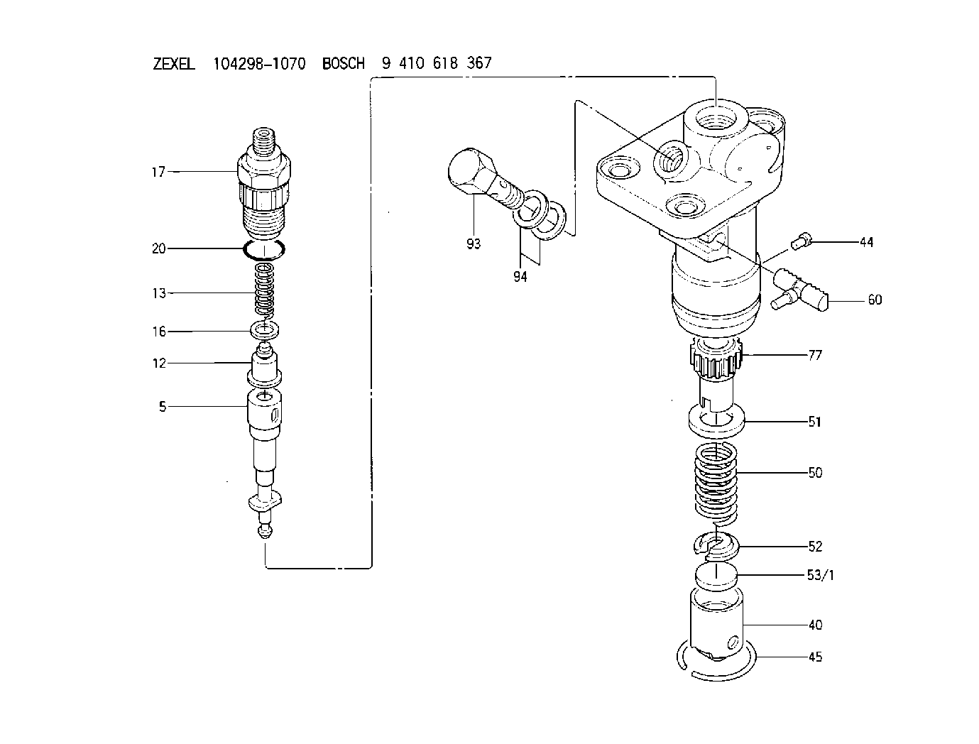
| 5. | [1] | 140163-4620 | PLUNGER-AND-BARREL ASSY |
| 12. | [1] | 140110-3720 | DELIVERY-VALVE ASSEMBLY |
| 13. | [1] | 140112-1700 | COMPRESSION SPRING |
| 16. | [1] | 140115-1400 | GASKET |
| 17. | [1] | 140116-6720 | FITTING |
| 20. | [1] | 016500-1520 | O-RING |
| 40. | [1] | 140200-1620 | TAPPET |
| 44. | [1] | 140212-0300 | BEARING PIN |
| 45. | [1] | 140213-0600 | LOCKING WASHER |
| 50. | [1] | 140215-1900 | COMPRESSION SPRING |
| 51. | [1] | 140216-0800 | SLOTTED WASHER |
| 52. | [1] | 140217-2200 | SLOTTED WASHER |
| 53/1. | [1] | 140217-5000 | PLATE D19T2.60 |
| 53/1. | [1] | 140217-5100 | PLATE D19T2.65 |
| 53/1. | [1] | 140217-5200 | PLATE D19T2.70 |
| 53/1. | [1] | 140217-5300 | PLATE D19T2.75 |
| 53/1. | [1] | 140217-5400 | PLATE D19T2.80 |
| 53/1. | [1] | 140217-5500 | PLATE D19T2.85 |
| 53/1. | [1] | 140217-5600 | PLATE D19T2.90 |
| 53/1. | [1] | 140217-5700 | PLATE D19T2.95 |
| 53/1. | [1] | 140217-5800 | PLATE D19T3.00 |
| 53/1. | [1] | 140217-5900 | PLATE D19T3.05 |
| 53/1. | [1] | 140217-6000 | PLATE D19T3.10 |
| 53/1. | [1] | 140217-6100 | PLATE D19T3.15 |
| 53/1. | [1] | 140217-6200 | PLATE D19T3.20 |
| 53/1. | [1] | 140217-6300 | PLATE D19T3.25 |
| 53/1. | [1] | 140217-6400 | PLATE D19T3.30 |
| 53/1. | [1] | 140217-6500 | PLATE D19T3.35 |
| 53/1. | [1] | 140217-6600 | PLATE D19T3.40 |
| 53/1. | [1] | 140217-6700 | PLATE D19T3.45 |
| 53/1. | [1] | 140217-6800 | PLATE D19T3.50 |
| 53/1. | [1] | 140217-6900 | PLATE D19T3.55 |
| 53/1. | [1] | 140217-7000 | PLATE D19T3.60 |
| 53/1. | [1] | 140217-7100 | PLATE D19T3.65 |
| 53/1. | [1] | 140217-7200 | PLATE D19T3.70 |
| 53/1. | [1] | 140217-7300 | PLATE D19T3.75 |
| 53/1. | [1] | 140217-7400 | PLATE D19T3.80 |
| 53/1. | [1] | 140217-7500 | PLATE D19T3.85 |
| 53/1. | [1] | 140217-7600 | PLATE D19T3.90 |
| 53/1. | [1] | 140217-7700 | PLATE D19T3.95 |
| 53/1. | [1] | 140217-7800 | PLATE D19T4.00 |
| 53/1. | [1] | 140217-7900 | PLATE D19T4.05 |
| 53/1. | [1] | 140217-8000 | PLATE D19T4.10 |
| 53/1. | [1] | 140253-2000 | PLATE |
| 53/1. | [1] | 140253-2100 | PLATE |
| 53/1. | [1] | 140253-2200 | PLATE |
| 53/1. | [1] | 140253-2300 | PLATE |
| 53/1. | [1] | 140253-2400 | PLATE |
| 53/1. | [1] | 140253-2500 | PLATE |
| 53/1. | [1] | 140253-2600 | PLATE |
| 53/1. | [1] | 140253-2700 | PLATE |
| 53/1. | [1] | 140253-2800 | PLATE |
| 53/1. | [1] | 140253-2900 | PLATE |
| 53/1. | [1] | 140253-3000 | PLATE |
| 53/1. | [1] | 140253-3100 | PLATE |
| 53/1. | [1] | 140253-3200 | PLATE |
| 53/1. | [1] | 140253-3300 | PLATE |
| 53/1. | [1] | 140253-3400 | PLATE |
| 53/1. | [1] | 140253-3500 | PLATE |
| 53/1. | [1] | 140253-3600 | PLATE |
| 53/1. | [1] | 140253-3700 | PLATE |
| 53/1. | [1] | 140253-3800 | PLATE |
| 53/1. | [1] | 140253-3900 | PLATE |
| 53/1. | [1] | 140253-4000 | PLATE |
| 53/1. | [1] | 140253-4100 | PLATE |
| 53/1. | [1] | 140253-4200 | PLATE |
| 53/1. | [1] | 140253-4300 | PLATE |
| 53/1. | [1] | 140253-4400 | PLATE |
| 53/1. | [1] | 140253-4500 | PLATE |
| 53/1. | [1] | 140253-4600 | PLATE |
| 53/1. | [1] | 140253-4700 | PLATE |
| 53/1. | [1] | 140253-4800 | PLATE |
| 53/1. | [1] | 140253-4900 | PLATE |
| 60. | [1] | 140243-0920 | CONTROL RACK |
| 77. | [1] | 140241-2700 | CONTROL SLEEVE |
| 93. | [1] | 140402-1600 | EYE BOLT |
| 94. | [2] | 026512-1540 | GASKET D15.4&12.2T1.50 |
Include in #2:
104298-1070
as INJECTION-PUMP ASSEMBLY
Cross reference number
Zexel num
Bosch num
Firm num
Name
104298-1070
1T07151012 KUBOTA
FUEL-INJECTION PUMP
B K 23DA FUEL INJECTION PUMP PFR-1KD PFR
B K 23DA FUEL INJECTION PUMP PFR-1KD PFR
104298-1070
1T07151011 KUBOTA
FUEL-INJECTION PUMP
A K 23DA FUEL INJECTION PUMP PFR-1KD PFR
A K 23DA FUEL INJECTION PUMP PFR-1KD PFR
Information:
Introduction
Tools are now available for the 6V4830 Fixture Group for removal and replacement of tappet springs on 3500 Unit Injectors.
Type 2 Fuel Injector. (1) Spring. (2) Rack Bar.
(3) 6V4830 Fixture Group. (4) 4C9279 Plate Assembly.Use fixture group (3) and plate assembly (4) along with the procedure in this instruction to remove and install tappet springs on injectors.Do not perform any procedure, outlined in this publication, or order any parts until you read and understand the information contained within.Removal and Installation of Fuel Injector Tappet Springs
Take care not to damage, drop, or jar the internal parts of the injector. Injector parts must be clean when reassembled. Place a light coating of clean diesel fuel, kerosene, or calibration fluid on the moving internal components during assembly.
* Clean the outside of the injector before disassembly. Install good O-ring seals on the injector and then install a 6V4172 Cleaning Sleeve. Wash the outside of the injector with solvents and a brush. Dry with pressure air.
Pressure air can cause personal injury. When using pressure air for cleaning, wear a protective face shield, protective clothing and protective shoes.The maximum air pressure must be below 205 kPa (30 psi) for cleaning purposes.
1. Remove existing plate and secure plate assembly (4) to fixture group (3).2. Remove O-ring seals from the injector prior to placing injector into fixture.3. Place injector into fixture with spring up as shown. Rack bar (2) on injector is to be extended out so that it is locked into position by two pins on plate assembly (4). 4. Using the handle of the fixture group, compress injector spring (tappet) (5) so that lock pin (6) can be pushed IN to release the tappet assembly from the injector body. 5. Remove tappet assembly from the injector body. Remove and discard old spring. Place the injector plunger on a soft clean cloth to avoid handling the plunger. Excessive handling will remove the fuel on the plunger and may result in corroding the plunger if it is left out for an extended period of time.6. Install new spring on injector body. 7. Locate the punched dot (.)(7) on the top end of the gear after it is pulled out of the body. Using a yellow magic marker, paint the whole length of the tooth that is 180° opposite the punched dot.
Injector Assembly (shown without spring).8. As the tappet/plunger assembly is inserted into the body, the yellow colored tooth on the gear should be visible in the center of the slot for the tappet lock pin.
Injector Assembly (shown without spring). 9. With the colored tooth visible in the slot of the injector body, a pin or long narrow screw driver is needed to position the gear to engage rack and pinion teeth after which the tappet assembly will drop into place.10. Using the 6V4830 Fixture Group, apply pressure on tappet (5) to compress the spring so the pin pops out and locks the tappet assembly in place.11. Remove the injector from the fixture. Push and pull the