Information fuel-injection pump
BOSCH
9 410 617 340
9410617340
ZEXEL
104293-2010
1042932010

Rating:
Components :
| 0. | INJECTION-PUMP ASSEMBLY | 104293-2010 |
| 1. | _ | |
| 2. | FUEL INJECTION PUMP | |
| 3. | NUMBER PLATE | |
| 4. | _ | |
| 5. | CAPSULE | |
| 6. | ADJUSTING DEVICE | |
| 7. | NOZZLE AND HOLDER ASSY | |
| 8. | Nozzle and Holder | |
| 9. | Open Pre:MPa(Kqf/cm2) | |
| 10. | NOZZLE-HOLDER | |
| 11. | NOZZLE |
Scheme ###:
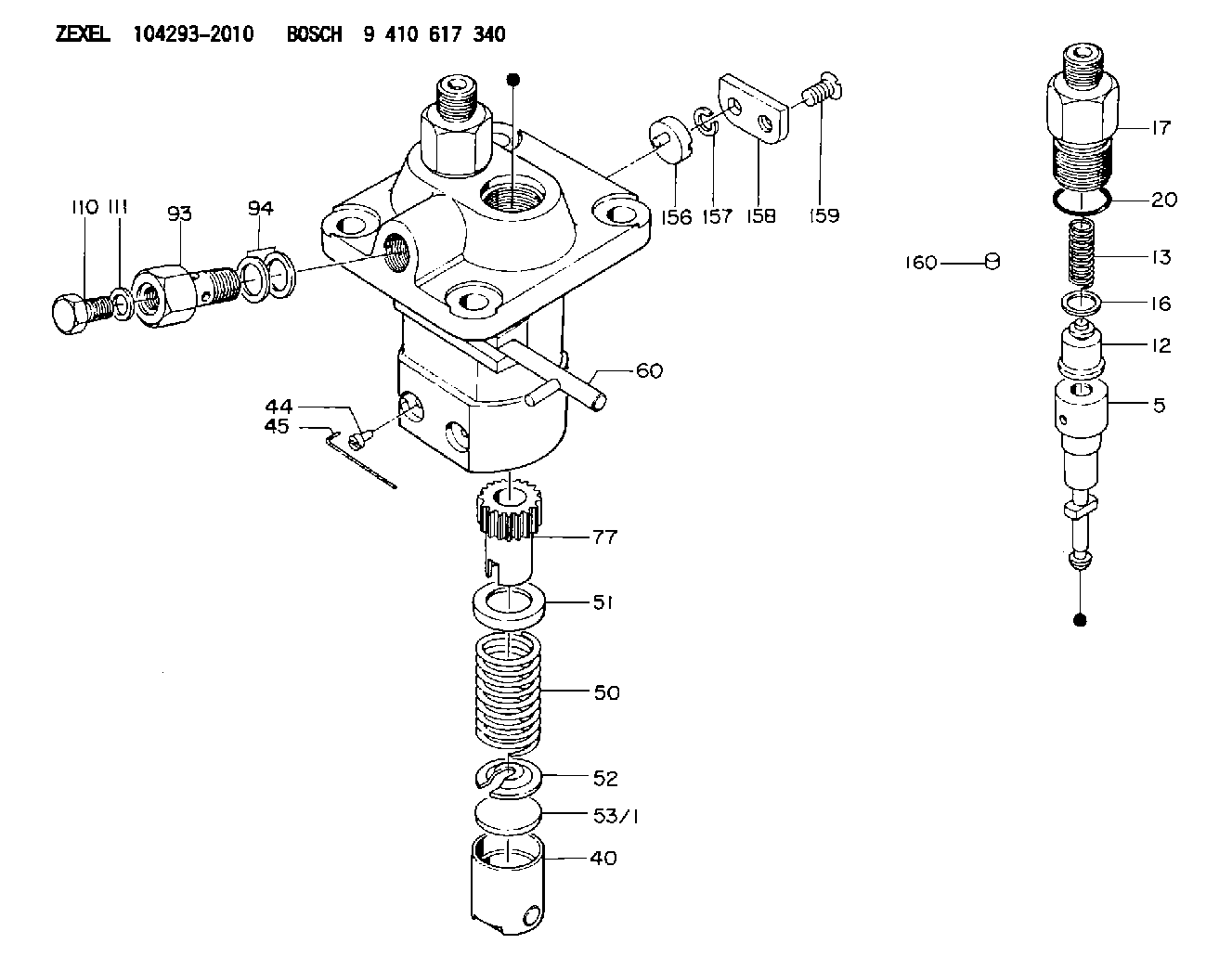
| 5. | [2] | 140151-9020 | PLUNGER-AND-BARREL ASSY |
| 12. | [2] | 140110-3720 | DELIVERY-VALVE ASSEMBLY |
| 13. | [2] | 140112-1700 | COMPRESSION SPRING |
| 16. | [2] | 140115-1400 | GASKET |
| 17. | [2] | 140116-4800 | FITTING |
| 20. | [2] | 016500-1520 | O-RING |
| 40. | [2] | 140200-1620 | TAPPET |
| 44. | [2] | 140212-0300 | BEARING PIN |
| 45. | [1] | 140213-0400 | WIRE |
| 50. | [2] | 140215-1200 | COMPRESSION SPRING |
| 51. | [2] | 140216-0800 | SLOTTED WASHER |
| 52. | [2] | 140217-2200 | SLOTTED WASHER |
| 53/1. | [1] | 140217-5000 | PLATE D19T2.60 |
| 53/1. | [1] | 140217-5100 | PLATE D19T2.65 |
| 53/1. | [1] | 140217-5200 | PLATE D19T2.70 |
| 53/1. | [1] | 140217-5300 | PLATE D19T2.75 |
| 53/1. | [1] | 140217-5400 | PLATE D19T2.80 |
| 53/1. | [1] | 140217-5500 | PLATE D19T2.85 |
| 53/1. | [1] | 140217-5600 | PLATE D19T2.90 |
| 53/1. | [1] | 140217-5700 | PLATE D19T2.95 |
| 53/1. | [1] | 140217-5800 | PLATE D19T3.00 |
| 53/1. | [1] | 140217-5900 | PLATE D19T3.05 |
| 53/1. | [1] | 140217-6000 | PLATE D19T3.10 |
| 53/1. | [1] | 140217-6100 | PLATE D19T3.15 |
| 53/1. | [1] | 140217-6200 | PLATE D19T3.20 |
| 53/1. | [1] | 140217-6300 | PLATE D19T3.25 |
| 53/1. | [1] | 140217-6400 | PLATE D19T3.30 |
| 53/1. | [1] | 140217-6500 | PLATE D19T3.35 |
| 53/1. | [1] | 140217-6600 | PLATE D19T3.40 |
| 53/1. | [1] | 140217-6700 | PLATE D19T3.45 |
| 53/1. | [1] | 140217-6800 | PLATE D19T3.50 |
| 53/1. | [1] | 140217-6900 | PLATE D19T3.55 |
| 53/1. | [1] | 140217-7000 | PLATE D19T3.60 |
| 53/1. | [1] | 140217-7100 | PLATE D19T3.65 |
| 53/1. | [1] | 140217-7200 | PLATE D19T3.70 |
| 53/1. | [1] | 140217-7300 | PLATE D19T3.75 |
| 53/1. | [1] | 140217-7400 | PLATE D19T3.80 |
| 53/1. | [1] | 140217-7500 | PLATE D19T3.85 |
| 53/1. | [1] | 140217-7600 | PLATE D19T3.90 |
| 53/1. | [1] | 140217-7700 | PLATE D19T3.95 |
| 53/1. | [1] | 140217-7800 | PLATE D19T4.00 |
| 53/1. | [1] | 140217-7900 | PLATE D19T4.05 |
| 53/1. | [1] | 140217-8000 | PLATE D19T4.10 |
| 53/1. | [1] | 140253-2000 | PLATE |
| 53/1. | [1] | 140253-2100 | PLATE |
| 53/1. | [1] | 140253-2200 | PLATE |
| 53/1. | [1] | 140253-2300 | PLATE |
| 53/1. | [1] | 140253-2400 | PLATE |
| 53/1. | [1] | 140253-2500 | PLATE |
| 53/1. | [1] | 140253-2600 | PLATE |
| 53/1. | [1] | 140253-2700 | PLATE |
| 53/1. | [1] | 140253-2800 | PLATE |
| 53/1. | [1] | 140253-2900 | PLATE |
| 53/1. | [1] | 140253-3000 | PLATE |
| 53/1. | [1] | 140253-3100 | PLATE |
| 53/1. | [1] | 140253-3200 | PLATE |
| 53/1. | [1] | 140253-3300 | PLATE |
| 53/1. | [1] | 140253-3400 | PLATE |
| 53/1. | [1] | 140253-3500 | PLATE |
| 53/1. | [1] | 140253-3600 | PLATE |
| 53/1. | [1] | 140253-3700 | PLATE |
| 53/1. | [1] | 140253-3800 | PLATE |
| 53/1. | [1] | 140253-3900 | PLATE |
| 53/1. | [1] | 140253-4000 | PLATE |
| 53/1. | [1] | 140253-4100 | PLATE |
| 53/1. | [1] | 140253-4200 | PLATE |
| 53/1. | [1] | 140253-4300 | PLATE |
| 53/1. | [1] | 140253-4400 | PLATE |
| 53/1. | [1] | 140253-4500 | PLATE |
| 53/1. | [1] | 140253-4600 | PLATE |
| 53/1. | [1] | 140253-4700 | PLATE |
| 53/1. | [1] | 140253-4800 | PLATE |
| 53/1. | [1] | 140253-4900 | PLATE |
| 60. | [1] | 140230-8320 | CONTROL RACK |
| 77. | [2] | 140241-2700 | CONTROL SLEEVE |
| 93. | [1] | 140402-0800 | EYE BOLT |
| 94. | [2] | 026512-1540 | GASKET D15.4&12.2T1.50 |
| 110. | [1] | 140420-1400 | BLEEDER SCREW |
| 111. | [1] | 026508-1240 | GASKET D11.9&8.2T1 |
| 156. | [1] | 140255-0000 | BEARING PIN |
| 157. | [1] | 029320-6010 | LOCKING WASHER |
| 158. | [1] | 140256-0300 | COVER |
| 159. | [1] | 010735-1020 | FLAT-HEAD SCREW M5P0.9L10 |
| 160. | [1] | 140423-0100 | CAPSULE |
Cross reference number
Zexel num
Bosch num
Firm num
Name
Information:
(a)When regrinding journals of the crankshaft, be sure to refinish all journals to the same dimension.(b)Finish the fillet radius to R3 mm [0.1181 in.].
Crankshaft fillet finishing dimension (2)Inspection of Oil Seal Contact Surface
Check the oil seal contact surface of the crankshaft back-end, and, if the crankshaft face has been excessively worn by the oil seal, replace the oil seal and oil sleeve with replacement parts.
Inspection of oil seal contact surface(1) Installation of oil seal sleeveTo install the oil seal sleeve, coat the inner surface of the sleeve with oil, and use the crankshaft sleeve installer for driving the sleeve into place.
Be careful not to dent or scratch the outer surface of the oil seal sleeve.
Inspection of oil seal sleeveWhen the oil seal slinger becomes worn after engine operation, remove the oil seal sleeve by following the procedure below, and replace it with a replacement oil seal assembly (oil seal and oil seal sleeve).
Inspection of oil seal contact surface(2) Removal of oil seal sleeveAt three locations on the sleeve end face, hold a chisel at a right angle to the sleeve and strike with a hammer, and remove the sleeve when it becomes loose.If this method does not allow the removal of the sleeve, hold the chisel in the axial direction and lightly tap to expand and loosen the sleeve.
Be careful not to damage the crankshaft with the chisel when removing the oil seal sleeve.
Removal of oil seal sleeveMeasurement of Crankshaft Deflection
Support the crankshaft on its front and rear journals in V-blocks, and measure the runout at the center journal with a dial gage. Compare the amount of runout with the standard. If the runout is small, correct by grinding. If the runout is large, straighten with a press.If the runout exceeds the limit significantly, replace the crankshaft.
Measurement of crankshaft deflectionRemoval of Crankshaft Gear
Use the gear puller to remove the crankshaft gear. Do not remove the crankshaft gear unless the crankshaft or gear is replaced.
Removal of crankshaft gearInstallation of Crankshaft Gear
(1) Heat the gear to a temperature of 100 to 150 °C [212 to 302 °F].(2) Install the key to the crankshaft.(3) Align the gear with key and insert the gear fully.
Installation of crankshaft gearMeasurement of Cylinder Bore
(1) Using a cylinder gage, measure the cylinder bore and cylindricity. If the limit value is exceeded even at one place, bore all cylinders and replace the pistons and piston rings with oversize pistons and piston rings. Measure at three locations each in directions A and B shown in the diagram.
Measurement of inside diameter of cylinder(2) Boring of cylinders(a) Since there are two piston oversizes (0.25 mm [0.0098 in.] and 0.50 mm [0.0197 in.] oversize) as indicated above, determine the appropriate piston size to be used based on the largest cylinder bore diameter.(b) Measure the outside diameter of the piston to be used. The piston diameter measuring points are shown in the diagram.(c) Based on the measurements of the piston outside diameter, calculate the finishing dimension to be achieved by boring.A: Piston