Information fuel-injection pump
BOSCH
9 410 617 027
9410617027
ZEXEL
104285-4050
1042854050
Rating:
Components :
| 0. | INJECTION-PUMP ASSEMBLY | 104285-4050 |
| 1. | _ | |
| 2. | FUEL INJECTION PUMP | |
| 3. | NUMBER PLATE | |
| 4. | _ | |
| 5. | CAPSULE | |
| 6. | ADJUSTING DEVICE | |
| 7. | NOZZLE AND HOLDER ASSY | |
| 8. | Nozzle and Holder | |
| 9. | Open Pre:MPa(Kqf/cm2) | |
| 10. | NOZZLE-HOLDER | |
| 11. | NOZZLE |
Scheme ###:
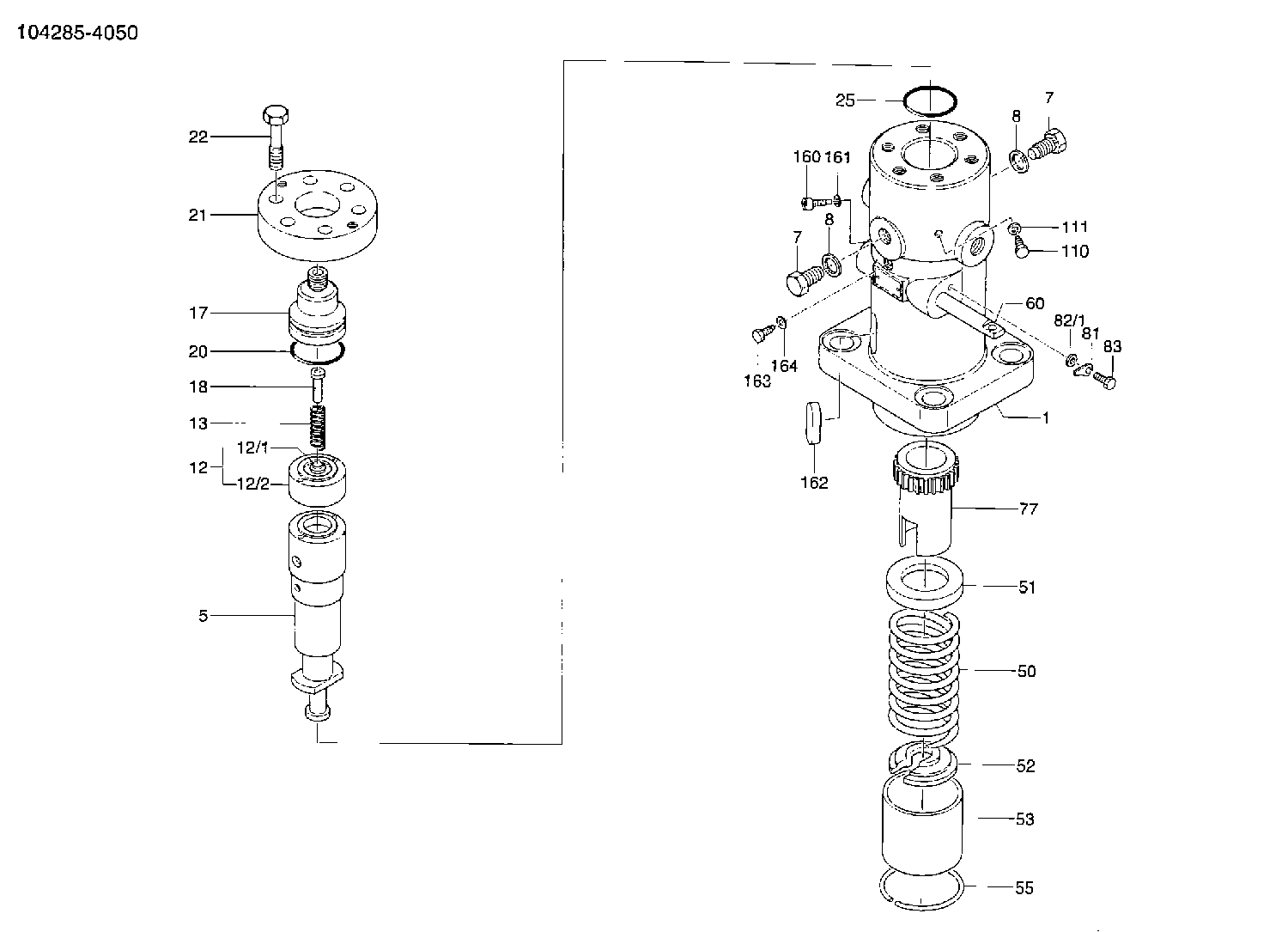
| 1. | [1] | 141053-6921 | PUMP HOUSING |
| 5. | [1] | 141177-9320 | PLUNGER-AND-BARREL ASSY E105 |
| 7. | [2] | 141133-0400 | CAPSULE |
| 7. | [2] | 141133-0400 | CAPSULE |
| 8. | [2] | 141403-0800 | GASKET |
| 8. | [2] | 141403-0800 | GASKET |
| 12. | [1] | 141142-0320 | DELIVERY-VALVE ASSEMBLY E18 |
| 12/1. | [1] | 141142-0300 | VALVE BODY |
| 12/2. | [1] | 141141-3500 | SEAT;D.V |
| 13. | [1] | 141112-6300 | COMPRESSION SPRING |
| 17. | [1] | 141136-3901 | FITTING |
| 18. | [1] | 141117-7200 | FILLER PIECE |
| 20. | [1] | 141118-2100 | O-RING |
| 21. | [1] | 141119-3500 | FLANGE BUSHING |
| 22. | [6] | 141124-1200 | BLEEDER SCREW |
| 25. | [1] | 141482-9700 | O-RING |
| 50. | [1] | 141215-5301 | COMPRESSION SPRING |
| 51. | [1] | 141216-3600 | SLOTTED WASHER |
| 52. | [1] | 141217-5400 | SLOTTED WASHER |
| 53. | [1] | 141218-7820 | GUIDE |
| 55. | [1] | 141220-0500 | LOCKING WASHER |
| 60. | [1] | 141244-5500 | CONTROL RACK |
| 77. | [1] | 141241-8300 | CONTROL SLEEVE |
| 81. | [1] | 141245-2000 | POINTER |
| 82/1. | [0] | 023500-6210 | PLAIN WASHER D11&6.4T1.5 |
| 82/1. | [0] | 029300-6010 | PLAIN WASHER D11&6.4T0.8 |
| 82/1. | [0] | 029300-6020 | PLAIN WASHER D11&6.4T0.35 |
| 83. | [1] | 020006-1440 | BLEEDER SCREW |
| 110. | [1] | 141420-0600 | BLEEDER SCREW |
| 111. | [1] | 141107-0500 | GASKET |
| 160. | [1] | 141418-1300 | SET OF NUTS |
| 161. | [1] | 141107-0800 | GASKET |
| 162. | [1] | 141480-0800 | COVER |
| 163. | [1] | 373658-1400 | CAPSULE |
| 164. | [1] | 141107-0500 | GASKET |
Cross reference number
Zexel num
Bosch num
Firm num
Name
Information:
(5) Removing Alternator
(a) Disconnect the battery cables.(b) Disconnect the lead from terminal B at the rear of the alternator.(c) Remove the alternator connector.(d) Loose the alternator adjusting bolt (1) and support bolt (2), then push the alternator toward the engine and remove the fan belt.(e) Remove the alternator.
Removing alternator(6) Removing Starter
(a) Disconnect the battery's (-) and (+) terminals in that sequence.(b) Disconnect the starter wiring (1).(c) Remove the starter's two mounting bolts (2), then remove the starter (3).
Removing starter(7) Removing Oil Filter
(a) The oil filter (2) must be replaced every 100 hours of use.(b) Remove the oil filter using a filter wrench (1).
Removing oil filter(8) Removing Fuel Filter
(a) Remove the fuel hose (1) that leads to the fuel injection pump.(b) Remove the fuel filter (2) from the engine.
Removing fuel filter(9) Removing Fuel Pipes
(a) Remove the clamps from the four fuel pipes (1), then disconnect the fuel pipes from the engine and from the injection pump.(b) Remove the lock nuts (2) and the fuel leak-off pipe (3) from the injection nozzle.
Removing Fuel Pipes
To keep dirt out of the fuel system, fit rubber caps over the parts of the injection pump and injector inlet connectors from which the injection pipes are disconnected.
(10) Removing Injection Pump
Removing Injection Pump(1) Fuel hose(2) Fuel pipe(3) Tie rod cover(4) Tie rod spring(5) Tie rod(6) Injection pump(7) Adjustment shim(8) Control rack pin(a) Remove the tie rod cover (3).(b) Using long-nosed pliers, remove the tie rod spring (4) from the control rack pin (8) and from the governor lever pin.(c) Remove the tie rod (5).
Removing tie rod(d) Remove the injection pump (6) and the adjustment shim (7).
Removing injection pump(11) Removing ETS Solenoid
Loose the nut (1) and remove the ETS solenoid (2).
Removing ETS solenoid(12) Removing Oil Pump
Remove the oil pump's four mounting bolts, then remove the oil pump (1).
Removing oil pump(13) Removing Injection Nozzle
(a) Remove all lock nuts (1) (4 pieces).(b) Remove fuel leak-off pipe (2) and fuel return gasket (3).(c) Remove fuel injection nozzle (4) and holder gasket (5).
Removing injection nozzleRefitting Accessories
General Points
Refit accessories by following the removal procedures in reverse. After refitting accessories, perform the following:(1) Pour the specified amount of engine oil into the engine.(2) Pour coolant into the coolant system.(3) To facilitate starting, pour engine oil into the governor's hydraulic oil filter via the hole of the air bleeding plug.(4) Make sure no oil or coolant is leaking from joints and connections.(5) Air-bleed the fuel system.(6) After refitting the injection pump (see the instructions below), be sure to inspect and adjust the injection timing.Installing Injection Pump
Installation should be performed basically by following the removal procedure in reverse. The following operations must also be performed.(1) Bleeding Air from Fuel System
Bleeding air from fuel system(a) Feed fuel to the engine by turning the key to the ON position. Then, loosen the air vent screw (1), allow air in the filter to be expelled, and retighten the screw.(b) Loosen air vent screws (2) and (3) on the injection pump in that sequence to bleed air from the