Information fuel-injection pump
BOSCH
F 01G 09Y 01J
f01g09y01j
ZEXEL
104285-4011
1042854011
Rating:
Components :
| 0. | INJECTION-PUMP ASSEMBLY | 104285-4011 |
| 1. | _ | |
| 2. | FUEL INJECTION PUMP | |
| 3. | NUMBER PLATE | |
| 4. | _ | |
| 5. | CAPSULE | |
| 6. | ADJUSTING DEVICE | |
| 7. | NOZZLE AND HOLDER ASSY | |
| 8. | Nozzle and Holder | |
| 9. | Open Pre:MPa(Kqf/cm2) | |
| 10. | NOZZLE-HOLDER | |
| 11. | NOZZLE |
Scheme ###:
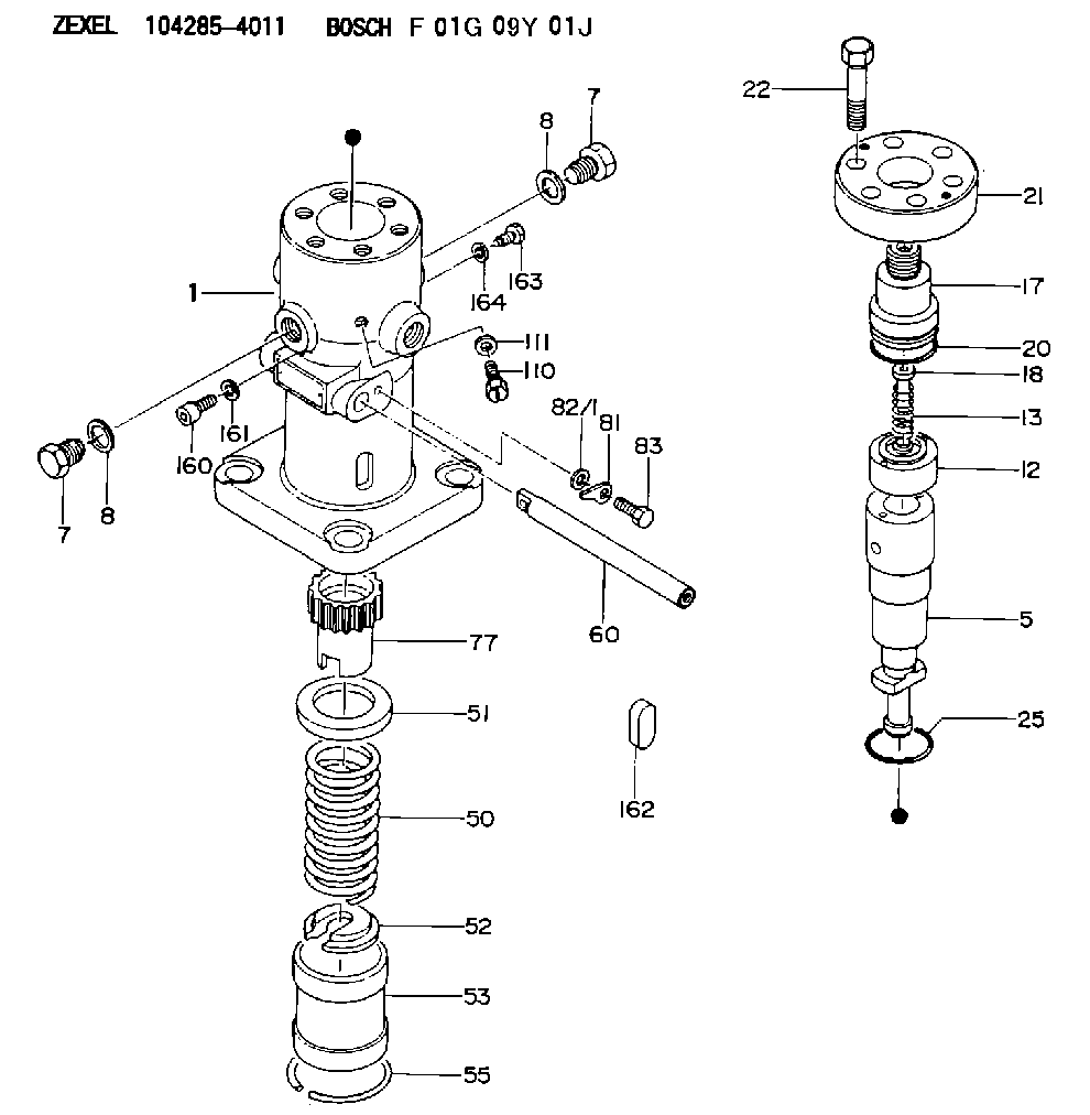
| 1. | [1] | 141053-0520 | PUMP HOUSING |
| 5. | [1] | 141177-5820 | PLUNGER-AND-BARREL ASSY E68 |
| 7. | [2] | 141133-0400 | CAPSULE |
| 7. | [2] | 141133-0400 | CAPSULE |
| 8. | [2] | 141403-0800 | GASKET |
| 8. | [2] | 141403-0800 | GASKET |
| 12. | [1] | 141140-6821 | DELIVERY-VALVE ASSEMBLY E30 |
| 13. | [1] | 141112-6300 | COMPRESSION SPRING |
| 17. | [1] | 141136-3901 | FITTING |
| 18. | [1] | 141117-7200 | FILLER PIECE |
| 20. | [1] | 141118-2100 | O-RING |
| 21. | [1] | 141119-3500 | FLANGE BUSHING |
| 22. | [6] | 141124-1200 | BLEEDER SCREW |
| 25. | [1] | 141482-9700 | O-RING |
| 50. | [1] | 141215-5301 | COMPRESSION SPRING |
| 51. | [1] | 141216-3600 | SLOTTED WASHER |
| 52. | [1] | 141217-5400 | SLOTTED WASHER |
| 53. | [1] | 141218-7820 | GUIDE |
| 55. | [1] | 141220-0500 | LOCKING WASHER |
| 60. | [1] | 141244-5500 | CONTROL RACK |
| 77. | [1] | 141241-7100 | CONTROL SLEEVE |
| 81. | [1] | 141245-2000 | POINTER |
| 82/1. | [0] | 023500-6210 | PLAIN WASHER D11&6.4T1.5 |
| 82/1. | [0] | 029300-6010 | PLAIN WASHER D11&6.4T0.8 |
| 82/1. | [0] | 029300-6020 | PLAIN WASHER D11&6.4T0.35 |
| 83. | [1] | 020006-1440 | BLEEDER SCREW |
| 110. | [1] | 141420-0600 | BLEEDER SCREW |
| 111. | [1] | 141107-0500 | GASKET |
| 160. | [1] | 141418-1300 | SET OF NUTS |
| 161. | [1] | 141107-0800 | GASKET |
| 162. | [1] | 141480-0800 | COVER |
| 163. | [1] | 010042-1620 | BLEEDER SCREW |
| 164. | [1] | 141107-0900 | GASKET |
Cross reference number
Zexel num
Bosch num
Firm num
Name
Information:
In this manual, specifications, service standards, adjustment procedures, disassembly procedures, inspection procedures, and reassembly procedures for the engine are shown in groups. The contents of each group are listed in the index and at the beginning of that group. For instructions on operation and periodic inspection, refer to the operation manual. For instructions on ordering replacement parts, refer to the parts catalog. For information on the engine's structure and function, refer to relevant training material.Items Shown in this Manual
(1) Parts mentioned in the text and shown exploded views are numbered in their disassembly sequences.(2) Inspections to be preformed during disassembly are shown in
in the exploded views.(3) Service standards for inspection and repair operations are indicated at relevant places in the text and in a table in Group 2.(4) The sequences in which parts should be reassembled during reassembly operations are shown under reassembly drawings in this manner:
(5) The symbols and headings shown below are used in this manual to highlight particularly important and safety-critical instruction.
Indicates a potentially hazardous situation which, if not avoided, can result in death or serious injury.
Indicates a potentially hazardous situation which, if not avoided, can result in minor or moderate injury.
Indicates a potentially hazardous situation which, if not avoided, can result in property damage.
Indicates important information or information which is useful for engine operation or maintenance.(6) With regard to tightening torques, points to which engine oil must be applied are labeled "Wet". Where there is no such indication, parts should be tightened in a dry condition.Terms Used in This Manual
Terms used in this manual are defined as follows:(1) Front and RearThe term "front" refers to the fan side of the engine, and the term "rear" applies to the flywheel side.(2) Left and RightThe term "left" and "right" apply to the sides of the engine as seen from the flywheel.(3) Service Standards* Standard ValueThis term indicates a designed nominal dimension, the designed dimension of a single part, the standard clearance between two parts after assembly, or a standard performance value for an assembly.* LimitThis term indicates a value beyond which a part is no longer usable in terms of performance and strength and must be repaired or replaced.