Information fuel-injection pump
BOSCH
9 410 617 432
9410617432
ZEXEL
104285-4010
1042854010
Rating:
Components :
| 0. | INJECTION-PUMP ASSEMBLY | 104285-4010 |
| 1. | _ | |
| 2. | FUEL INJECTION PUMP | |
| 3. | NUMBER PLATE | |
| 4. | _ | |
| 5. | CAPSULE | |
| 6. | ADJUSTING DEVICE | |
| 7. | NOZZLE AND HOLDER ASSY | |
| 8. | Nozzle and Holder | |
| 9. | Open Pre:MPa(Kqf/cm2) | |
| 10. | NOZZLE-HOLDER | |
| 11. | NOZZLE |
Scheme ###:
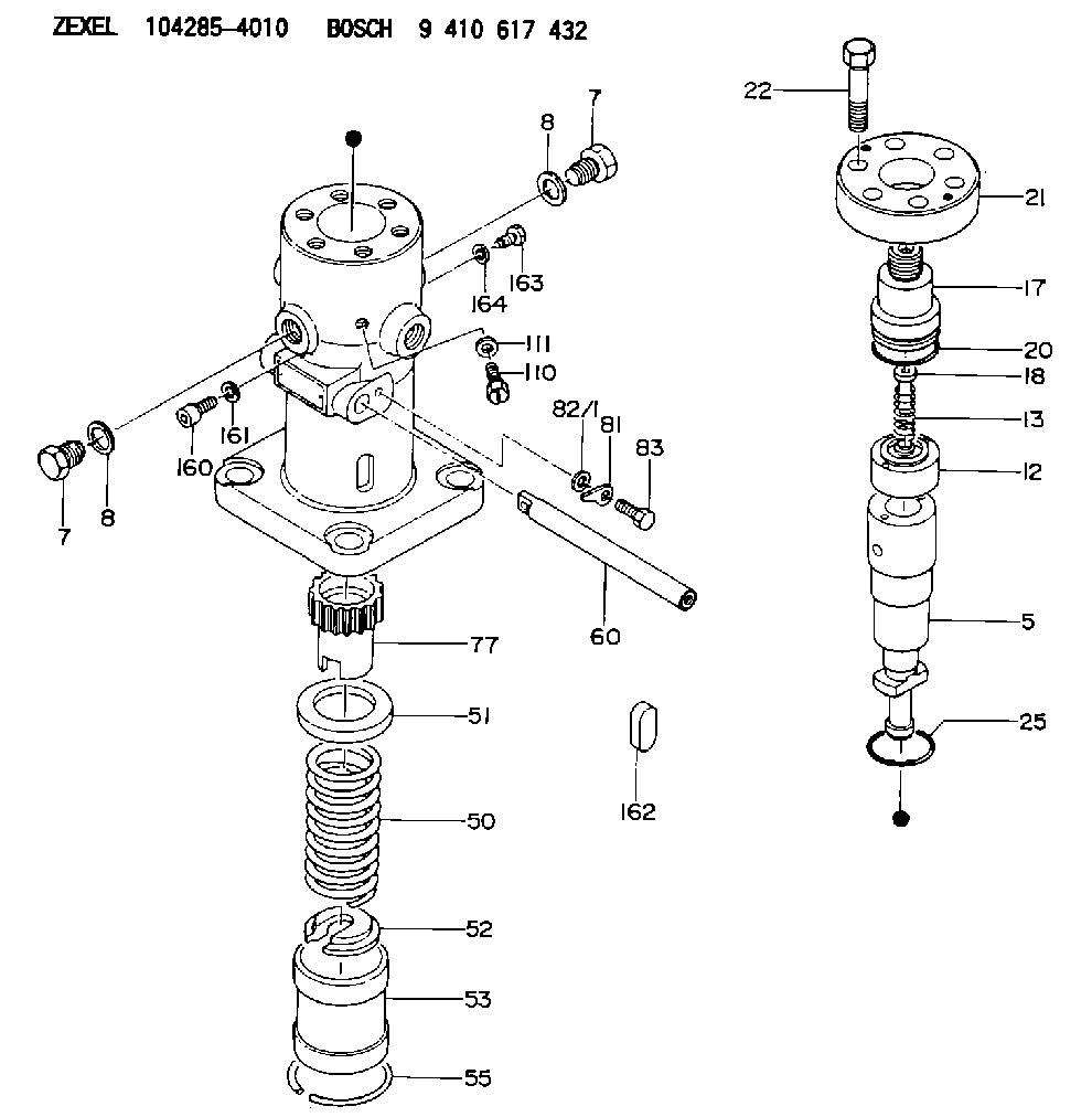
| 5. | [1] | 141177-5820 | PLUNGER-AND-BARREL ASSY |
| 7. | [2] | 141133-0400 | CAPSULE |
| 7. | [2] | 141133-0400 | CAPSULE |
| 8. | [2] | 141403-0800 | GASKET |
| 8. | [2] | 141403-0800 | GASKET |
| 12. | [1] | 141140-6820 | DELIVERY-VALVE ASSEMBLY |
| 13. | [1] | 141112-6300 | COMPRESSION SPRING |
| 17. | [1] | 141136-3901 | FITTING |
| 18. | [1] | 141117-7200 | FILLER PIECE |
| 20. | [1] | 141118-2100 | O-RING |
| 21. | [1] | 141119-3500 | FLANGE BUSHING |
| 22. | [6] | 141124-1200 | BLEEDER SCREW |
| 25. | [1] | 141482-9700 | O-RING |
| 50. | [1] | 141215-5301 | COMPRESSION SPRING |
| 51. | [1] | 141216-3600 | SLOTTED WASHER |
| 52. | [1] | 141217-5400 | SLOTTED WASHER |
| 53. | [1] | 141218-7820 | GUIDE |
| 55. | [1] | 141220-0500 | LOCKING WASHER |
| 60. | [1] | 141244-5500 | CONTROL RACK |
| 77. | [1] | 141241-7100 | CONTROL SLEEVE |
| 81. | [1] | 141245-2000 | POINTER |
| 82/1. | [0] | 023500-6210 | PLAIN WASHER D11&6.4T1.5 |
| 82/1. | [0] | 029300-6010 | PLAIN WASHER D11&6.4T0.8 |
| 82/1. | [0] | 029300-6020 | PLAIN WASHER D11&6.4T0.35 |
| 83. | [1] | 020006-1440 | BLEEDER SCREW M6P1L14 |
| 110. | [1] | 141420-0600 | BLEEDER SCREW |
| 111. | [1] | 141107-0500 | GASKET |
| 160. | [1] | 141418-1300 | SET OF NUTS |
| 161. | [1] | 141107-0800 | GASKET |
| 162. | [1] | 141480-0800 | COVER |
| 163. | [1] | 010042-1620 | BLEEDER SCREW M12P1.75L16 |
| 164. | [1] | 141107-0900 | GASKET |
Cross reference number
Zexel num
Bosch num
Firm num
Name
Information:
An additional 5 hours is allowed if the harness must replaced.
Product smu/age whichever comes first Caterpillar Dealer Suggested Customer Suggested
Parts % Labor Hrs% Parts % Labor Hrs% Parts % Labor Hrs%
*******Group 2*******
0-4000 hrs,
0-12 mo 100.0% 100.0% 0.0% 0.0% 0.0% 0.0%
This is a 3.0-hour job for Group 2
An additional 10 hours is allowed if the harness must replaced.
PARTS DISPOSITION
Handle the parts in accordance with your Warranty Bulletin on warranty parts handling.
Rework Procedure
Group Number 1
Injector Harness Inspection
-Raise the engine enclosure hood.
-Remove the air intake pipe connecting the air filter to the turbo inlet.
-Remove the valve covers.
-Inspect the injector harness wiring for contact between the harness and valve springs.
Image1.1.1
Repair
-If the harness is close to the valve spring, adjust the harness by disconnecting the injector connector rotating the connector 360 degrees and reconnecting it. This should slightly twist the wires and pull them away from the springs.
Image1.2.1
Injector Harness Replacement (If Necessary)
-If the injector harness has contacted the spring and cut the wire or exposed the wire, then replace the injector harness that is under the valve cover.
-When installing the new harness to the valve cover base make sure the tabs do not turn while torquing down the bolts(see the picture below). Keep the tabs straight, and this will help keep the wiring away from the valve springs.
Image1.3.1
Group Number 2
Injector Harness Inspection
-Remove the rear engine enclosure.
-Remove the clamp for flex boot on the air filter housing.
-Remove the rubber elbow on the inlet of the compressor side of the turbocharger.
-Remove the clamps called out in the photo for the turbocharger outlet pipe that connects to the aftercooler.
Image2.1.1
-Remove all three engine valve covers.
-Inspect the injector harness wiring for contact between the harness and valve springs.
Image2.2.1
Repair
-If the harness is close to the valve spring, adjust the harness by disconnecting the injector connector rotating the connector 360 degrees and reconnecting it. This should slightly twist the wires and pull them away from the springs.
Image2.3.1
Injector Harness Replacement (If Necessary)
-If the injector harness has contacted the spring and cut the wire or exposed the wire, then replace the injector harness that is under the valve cover.
-Remove the doors, hood, Clean Emissions Module (CEM) and mounting plate, and valve cover base.
-When installing the new harness to the valve cover base make sure the tabs do not turn while torquing down the bolts(see the picture below). Keep the tabs straight, and this will help keep the wiring away from the valve springs.
Image2.4.1
-Reinstall the previously removed hardware, and use the new 344-8311 exhaust clamp.
Image2.5.1