Information fuel-injection pump
BOSCH
9 410 617 527
9410617527
ZEXEL
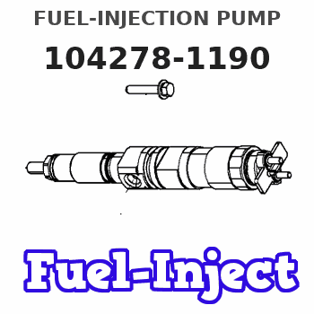
104278-1190
1042781190
NIIGATA-TEKKOU
77B47010B
77b47010b
Rating:
Components :
| 0. | INJECTION-PUMP ASSEMBLY | 104278-1190 |
| 1. | _ | |
| 2. | FUEL INJECTION PUMP | |
| 3. | NUMBER PLATE | |
| 4. | _ | |
| 5. | CAPSULE | |
| 6. | ADJUSTING DEVICE | |
| 7. | NOZZLE AND HOLDER ASSY | |
| 8. | Nozzle and Holder | |
| 9. | Open Pre:MPa(Kqf/cm2) | |
| 10. | NOZZLE-HOLDER | |
| 11. | NOZZLE |
Scheme ###:
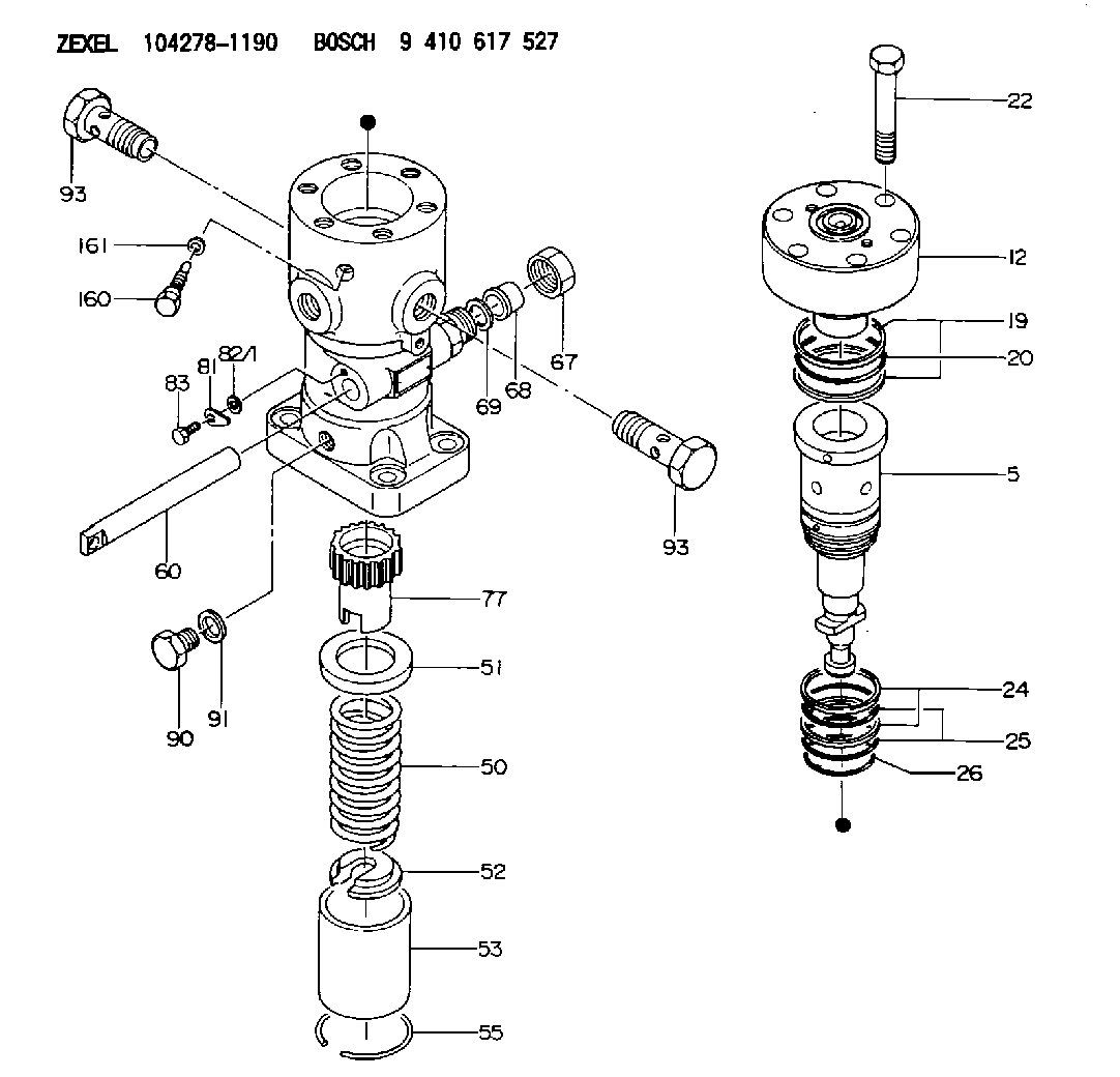
| 5. | [1] | 141187-6620 | PLUNGER-AND-BARREL ASSY |
| 12. | [1] | 141145-5020 | DELIVERY-VALVE ASSEMBLY |
| 19. | [2] | 016420-0850 | BACKUP RING |
| 20. | [1] | 141118-3100 | O-RING |
| 22. | [6] | 141124-4800 | BLEEDER SCREW |
| 24. | [2] | 016421-0750 | BACKUP RING |
| 25. | [2] | 141485-1500 | O-RING |
| 26. | [1] | 141118-3000 | O-RING |
| 50. | [1] | 141215-8300 | COMPRESSION SPRING |
| 51. | [1] | 141216-5800 | SLOTTED WASHER |
| 52. | [1] | 141217-8600 | SLOTTED WASHER |
| 53. | [1] | 141218-9900 | GUIDE |
| 55. | [1] | 141220-0700 | LOCKING WASHER |
| 60. | [1] | 141291-4800 | CONTROL RACK |
| 67. | [1] | 141439-4200 | UNION NUT |
| 68. | [1] | 141456-0800 | CONNECTOR |
| 69. | [1] | 141489-0200 | GASKET |
| 77. | [1] | 141292-1201 | CONTROL SLEEVE |
| 81. | [1] | 141245-2000 | POINTER |
| 82/1. | [0] | 023500-6210 | PLAIN WASHER D11&6.4T1.5 |
| 82/1. | [0] | 029300-6010 | PLAIN WASHER D11&6.4T0.8 |
| 82/1. | [0] | 029300-6020 | PLAIN WASHER D11&6.4T0.35 |
| 83. | [1] | 020006-1440 | BLEEDER SCREW M6P1L14 |
| 90. | [1] | 141418-3400 | CAPSULE |
| 91. | [1] | 026522-2740 | GASKET D26.9&22.2T1 |
| 93. | [2] | 141402-6600 | EYE BOLT |
| 93. | [2] | 141402-6600 | EYE BOLT |
| 160. | [1] | 141418-3000 | SET OF NUTS |
| 161. | [1] | 141403-2000 | GASKET |
Include in #2:
104278-1190
as INJECTION-PUMP ASSEMBLY
Cross reference number
Zexel num
Bosch num
Firm num
Name
Information:
Illustration 3 g06519715
DOC brackets
Illustration 4 g06519717
DOC
Connect the welding ground cable directly to the DOC brackets or the DOC that will be welded. Place the ground cable as close as possible to the weld. This location will reduce the possibility of welding current damage bearings, hydraulic components, electrical components, and ground straps.Note: If electrical components are used as a ground for the welder, current flow from the welder could severely damage the component. Current flow from the welder could also severely damage electrical components that are located between the welder ground and the weld.
Illustration 5 g06519270
Weld blanket
Illustration 6 g06519272
Use a weld blanket draped over the engine to protect the engine from weld splatter. Likely need 2 or 3 blankets to cover between DOCs and the entire engine from splatter.
Illustration 7 g06519274
Illustration 8 g06519277
(1) 536-5400 Plate
Clean the top surface in the two locations where plates (1) will be welded in place with either a wire wheel or a flap disk.Note: Failure to clean the weld area could result in poor weld quality.
Illustration 9 g06519323
(D1) 6 2 mm (0.236 0.079 inch)
Illustration 10 g06519297
(D1) 6 2 mm (0.236 0.079 inch)
(D2) 43 3 mm (1.693 0.118 inch)
Illustration 11 g06519348
(D2) 43 3 mm (1.693 0.118 inch)
Set the plates on the top side of the housing and line up perpendicular to the front face. Position the plates to dimension (D1) from the front edge of the top plate.
Position the plates to dimension (D2) from the far edge of the rounded plate. There is a chamfer and fillet weld that will make measurements less precise. Use a tape measure to position.Note: Etching marks may also be present on the top of the unit and can be used for further positional guidance.
Illustration 12 g06519373
(W1) Tack weld
With the plates in place, add tack welds (W1) to the plates shown in Illustration 12. Use 308L weld wire.
Illustration 13 g06519408
(W2) 50 to 100 mm (1.969 to 3.937 inch)
Skip fillet weld (W2) down the side of each plate and then weld at the ends of each plates. Use 308L weld wire.
Illustration 14 g06519430
Finished product
Verify the weld quality and look for the following:
Cracks
Porosity
Inclusions
Convexity/Excess Weld Material
Concavity/Under Fill
Excess Penetration
Lack of Penetration
Fillet Weld - Undersize
Lack of Fusion
Undercut
Toe Radius
Overlap
Poor Restarts/Tie-ins
Cleaning/Grinding
Spatter/Arc Strike/Wire Stub
Illustration 15 g06519435
Mark the new plates with "THIS SIDE UP".Note: Make sure that the text is visible and stands out on the DOC.