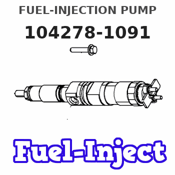
Information fuel-injection pump
BOSCH
9 410 617 651
9410617651
ZEXEL
104278-1091
1042781091
DAIHATSU
E406400150AB
e406400150ab
Rating:
Components :
| 0. | INJECTION-PUMP ASSEMBLY | 104278-1091 |
| 1. | _ | |
| 2. | FUEL INJECTION PUMP | |
| 3. | NUMBER PLATE | |
| 4. | _ | |
| 5. | CAPSULE | |
| 6. | ADJUSTING DEVICE | |
| 7. | NOZZLE AND HOLDER ASSY | |
| 8. | Nozzle and Holder | |
| 9. | Open Pre:MPa(Kqf/cm2) | |
| 10. | NOZZLE-HOLDER | |
| 11. | NOZZLE |
Scheme ###:
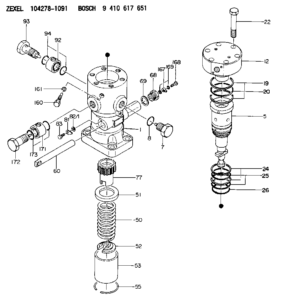
| 1. | [1] | 141054-6320 | PUMP HOUSING |
| 5. | [1] | 141187-6020 | PLUNGER-AND-BARREL ASSY |
| 7. | [1] | 141133-7400 | CAPSULE |
| 8. | [1] | 141485-1301 | O-RING |
| 12. | [1] | 141142-9620 | DELIVERY-VALVE ASSEMBLY |
| 19. | [2] | 016420-0850 | BACKUP RING |
| 20. | [1] | 141118-3100 | O-RING |
| 22. | [6] | 141124-4800 | BLEEDER SCREW |
| 24. | [2] | 016421-0750 | BACKUP RING |
| 25. | [2] | 141485-1501 | O-RING |
| 26. | [1] | 141118-3001 | O-RING |
| 50. | [1] | 141215-4801 | COMPRESSION SPRING |
| 51. | [1] | 141216-5800 | SLOTTED WASHER |
| 52. | [1] | 141217-8600 | SLOTTED WASHER |
| 53. | [1] | 141218-9300 | GUIDE |
| 55. | [1] | 141220-0700 | LOCKING WASHER |
| 60. | [1] | 141291-2000 | CONTROL RACK |
| 68. | [1] | 141405-3800 | CAPSULE |
| 69. | [1] | 141403-2100 | GASKET |
| 77. | [1] | 141292-2101 | CONTROL SLEEVE |
| 81. | [1] | 141245-2000 | POINTER |
| 82/1. | [0] | 023500-6210 | PLAIN WASHER D11&6.4T1.5 |
| 82/1. | [0] | 029300-6010 | PLAIN WASHER D11&6.4T0.8 |
| 82/1. | [0] | 029300-6020 | PLAIN WASHER D11&6.4T0.35 |
| 83. | [1] | 020006-1440 | BLEEDER SCREW M6P1L14 |
| 92. | [1] | 141401-5300 | INLET UNION |
| 93. | [1] | 141402-6600 | EYE BOLT |
| 94. | [2] | 141485-1301 | O-RING |
| 160. | [1] | 141418-3000 | SET OF NUTS |
| 161. | [1] | 141403-2000 | GASKET |
| 167. | [1] | 150948-0000 | INLET UNION |
| 168. | [1] | 150949-0100 | EYE BOLT |
| 169. | [2] | 150521-0800 | GASKET |
| 171. | [1] | 141401-5300 | INLET UNION |
| 172. | [1] | 141402-5700 | EYE BOLT |
| 173. | [2] | 141485-1301 | O-RING |
Include in #1:
101401-9445
as _
Include in #2:
104278-1091
as INJECTION-PUMP ASSEMBLY
Cross reference number
Zexel num
Bosch num
Firm num
Name
104278-1091
E406400150AB DAIHATSU
FUEL-INJECTION PUMP
K 24JW FUEL INJECTION PUMP PF-1TV PF
K 24JW FUEL INJECTION PUMP PF-1TV PF
104278-1091
E406400150AA NIIGATA-TEKKOU
FUEL-INJECTION PUMP
K 24JW FUEL INJECTION PUMP PF-1TV PF
K 24JW FUEL INJECTION PUMP PF-1TV PF
Information:
Introduction
The problem that is identified below does not have a known permanent solution. Until a permanent solution is known, use the solution that is identified below.Problem
DEF heated lines can get damaged during handling or other failure modes and leak diesel exhaust fluid on Clean Emission Module (CEM) and other components.Solution
Caterpillar is aware of this problem and is recommending the following interim corrective action.
Do not operate or work on this product unless you have read and understood the instruction and warnings in the relevant Operation and Maintenance Manuals and relevant service literature. Failure to follow the instructions or heed the warnings could result in injury or death. Proper care is your responsibility.
Rework Procedure
Note: This procedure is meant for temporary repair of a DEF line to allow the machine to be safely transported to the repair shop.
Table 1
Required Parts
Part Number Part Name
473-2053 Diesel Exhaust Fluid Lines Gp (5/16th 90 degree adapter)
473-2055 Diesel Exhaust Fluid Lines Gp (5/16th straight adapter)
473-2056 Diesel Exhaust Fluid Lines Gp (3/8th 90 degree adapter)
473-2057 Diesel Exhaust Fluid Lines Gp (38th 90 Straight adapter)
Table 2
Required Tools
Part Number Part Name
1U-7648 Tube Cutter
Illustration 1 g06433660
Cut the connector end on the corrugated section with the cutter.
Illustration 2 g06433665
Cut the two wires with a tie cutter.
Illustration 3 g06433668
Use a knife or sharp blade to cut the outer sheathing off. Ensure not to cut or damage the inner fluid hose.
Illustration 4 g06433669
Install the hose clamp provided first before installing the connector. Use appropriate size (3/8th or 5/16th) and type (90 degree or straight) fitting.
Illustration 5 g06433672
Fasten the clamp until the two jaws are either in contact or about 2 to 3 mm (0.08 to 0.1 inch) apart.