Information fuel-injection pump
BOSCH
9 410 618 068
9410618068
ZEXEL
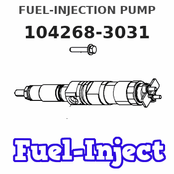
104268-3031
1042683031
NIIGATA-TEKKOU
7BA47011B
7ba47011b
Rating:
Components :
| 0. | INJECTION-PUMP ASSEMBLY | 104268-3031 |
| 1. | _ | |
| 2. | FUEL INJECTION PUMP | |
| 3. | NUMBER PLATE | |
| 4. | _ | |
| 5. | CAPSULE | |
| 6. | ADJUSTING DEVICE | |
| 7. | NOZZLE AND HOLDER ASSY | |
| 8. | Nozzle and Holder | |
| 9. | Open Pre:MPa(Kqf/cm2) | |
| 10. | NOZZLE-HOLDER | |
| 11. | NOZZLE |
Scheme ###:
| 1. | [1] | 141055-8300 | PUMP HOUSING |
| 5. | [1] | 141189-5420 | PLUNGER-AND-BARREL ASSY |
| 12. | [1] | 141145-6521 | DELIVERY-VALVE ASSEMBLY |
| 12/1. | [1] | 141146-2300 | SEAT;D.V. |
| 12/2. | [1] | 141138-1800 | FITTING |
| 12/3. | [1] | 141142-9100 | VALVE BODY |
| 12/4. | [1] | 141144-0500 | COMPRESSION SPRING |
| 12/5. | [1] | 141113-3201 | SLOTTED WASHER |
| 12/6. | [1] | 141145-8400 | VALVE BODY |
| 12/7. | [1] | 141112-8701 | COILED SPRING |
| 12/8. | [1] | 141113-2003 | FILLER PIECE |
| 12/9. | [2] | 010235-2520 | HEX-SOCKET-HEAD CAP SCREW |
| 16. | [1] | 150508-3100 | BEARING PIN |
| 18. | [8] | 141124-5900 | HEX-SOCKET-HEAD CAP SCREW |
| 21. | [1] | 141119-4901 | FLANGE BUSHING |
| 22. | [8] | 141124-6000 | BLEEDER SCREW |
| 24. | [2] | 016421-0600 | BACKUP RING |
| 25. | [3] | 141485-1002 | O-RING |
| 40. | [1] | 141200-3621 | TAPPET |
| 44. | [1] | 141212-0300 | BEARING PIN |
| 50. | [1] | 141215-9000 | COMPRESSION SPRING |
| 51. | [1] | 141216-7120 | SLOTTED WASHER |
| 52. | [1] | 141217-9600 | SLOTTED WASHER |
| 54. | [1] | 141450-2100 | PLATE |
| 56/1. | [1] | 141209-5000 | PLATE |
| 56/1. | [1] | 141209-5100 | PLATE |
| 56/1. | [1] | 141209-5200 | PLATE |
| 56/1. | [1] | 141209-5300 | PLATE |
| 56/1. | [1] | 141209-5400 | PLATE |
| 56/1. | [1] | 141209-5500 | PLATE |
| 56/1. | [1] | 141209-5600 | PLATE |
| 59. | [1] | 141485-0602 | O-RING |
| 60. | [1] | 141291-5200 | CONTROL RACK |
| 68. | [1] | 141405-4900 | ADAPTOR |
| 69. | [1] | 026520-2440 | GASKET D23.9&20.2T1 |
| 77. | [1] | 141292-3700 | CONTROL SLEEVE |
| 81. | [1] | 141245-2000 | POINTER |
| 82/1. | [0] | 023500-6210 | PLAIN WASHER D11&6.4T1.5 |
| 82/1. | [0] | 029300-6010 | PLAIN WASHER D11&6.4T0.8 |
| 82/1. | [0] | 029300-6020 | PLAIN WASHER D11&6.4T0.35 |
| 83. | [1] | 020006-1440 | BLEEDER SCREW M6P1L14 |
| 93. | [2] | 141402-3120 | EYE BOLT |
| 93. | [2] | 141402-3120 | EYE BOLT |
| 110. | [1] | 141418-2600 | SET OF NUTS |
| 111. | [1] | 141403-2000 | GASKET |
| 160. | [1] | 141418-2600 | SET OF NUTS |
| 161. | [1] | 141403-2000 | GASKET |
| 167. | [1] | 150948-0000 | INLET UNION |
| 168. | [1] | 150949-0100 | EYE BOLT |
| 169. | [2] | 150521-0800 | GASKET |
Include in #1:
101401-9011
as _
Include in #2:
104268-3031
as INJECTION-PUMP ASSEMBLY
Cross reference number
Zexel num
Bosch num
Firm num
Name
104268-3031
7BA47011B NIIGATA-TEKKOU
FUEL-INJECTION PUMP
K 24FS FUEL INJECTION PUMP PF-R1GS PF
K 24FS FUEL INJECTION PUMP PF-R1GS PF
Information:
Reference for 3500 Series Engines
Troubleshooting, M0080819, "3516E Engine for Tier 4 Final 994K Wheel Loaders".Testing and Adjusting, M0080815, "3516E Engine for Tier 4 Final 994K Wheel Loaders".Disassembly and Assembly, M0092351, "3516E Engines for Caterpillar Built Machines".Procedure
Note: If failed parts need to be shipped back, please cap off the ports using the caps from the new part.
What code are you troubleshooting? ____________________
Follow the correct troubleshooting procedure. Refer to "Reference for C175 Engines" and "Reference for 3500 Series Engines" Sections for correct media number to use.
When troubleshooting procedure requests the DEF quality check, DEF system inspection filter replacement or dosing accuracy, document those results in Table 1, Table 2, Table 3, and Table 4.
Table 1
DEF Quality Results
Step Instruction Completed (Yes/No) Result Comments Units
1 Follow the Testing and Adjusting procedure for "Diesel Exhaust Fluid Quality - Test"
2 DEF Contamination Test (include photo of test strip is possible) Pass/Fail
3 DEF concentration Test % at 20° C (68° F)
Table 2
DEF Tank Vent Line, Breather, and Cap Inspection Results
Step Instruction Completed (Yes/No) Result Comments Units
1 Follow the Testing and Adjusting procedure for "Diesel Exhaust Fluid Quality - Test"
2 DEF Contamination Test (include photo of test strip is possible)
3 DEF concentration Test
4 Remove the breather and inspect at the breather-to-vent line connections if debris is bypassing the breather (take photo)
5 Inspect the DEF tank manual fill cap for damage or debris (take photo)
6 Remove the DEF tank manual fill cap and inspect for damage or debris at the manual fill inlet to the tank (take a photo)
7 Remove the fill neck strainer and inspect for damage or debris (take a photo)
8 Clean or replace the strainer (if necessary) (take a photo)
Table 3
DEF Pump Filters Replaced
Step Instruction Completed (Yes/No) Result Comments Units
1 Prior to removal, inspect the DEF pump suction line fitting and DEF pump filter cap for any damage (take a photo)
2 Replace the DEF pump suction line filter fitting and DEF pump filter on the affected DEF pump. Comment on any notable damage or debris (take a photo of each post removal)
3 Bag, label (pump number in PETU, pump serial number, date removed), and return with pump.
Table 4
Dosing Accuracy Test
Step Instruction Completed (Yes/No) Result Comments Units
1 Follow the Testing and Adjusting, Aftertreatment SCR system Dosing Test.
2 For the pump in question, take a photograph of both DEF injectors, mounts, gaskets, bolts on the SCR inlet prior to removal. Ensure that the picture captures the DEF injector serial number and part number and not which position and which aftertreatment it was installed.
3 For the pump in question, remove both injectors from the SCR inlet.
4 Take a photograph of both DEF injector mounts on the SCR inlet and the tip of both DEF injectors.
5 Install each injector on the beaker.
6 Run the DEF System Dosing Accuracy test through Cat® ET for each injector.
7 Use the beaker to measure the amount of fluid from the dosing test for each injector. ____________________ml
____________________ml
8 Repeat the test for each injector to verify consistency.