Information fuel-injection pump
BOSCH
9 410 617 143
9410617143
ZEXEL
104268-1161
1042681161
DAIHATSU
E326470090EZ
e326470090ez
Rating:
Components :
| 0. | INJECTION-PUMP ASSEMBLY | 104268-1161 |
| 1. | _ | |
| 2. | FUEL INJECTION PUMP | |
| 3. | NUMBER PLATE | |
| 4. | _ | |
| 5. | CAPSULE | |
| 6. | ADJUSTING DEVICE | |
| 7. | NOZZLE AND HOLDER ASSY | |
| 8. | Nozzle and Holder | |
| 9. | Open Pre:MPa(Kqf/cm2) | |
| 10. | NOZZLE-HOLDER | |
| 11. | NOZZLE |
Scheme ###:
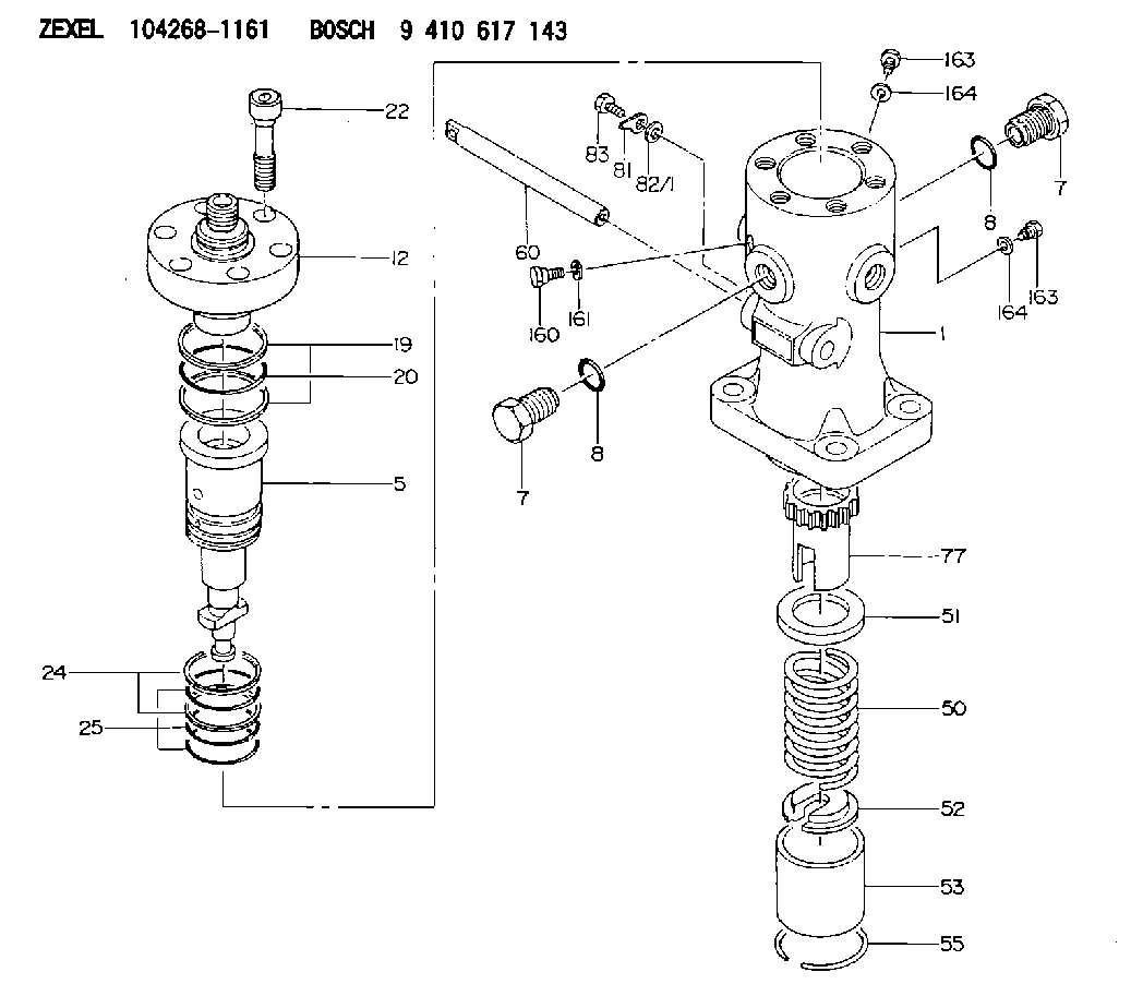
| 1. | [1] | 141055-0800 | PUMP HOUSING |
| 5. | [1] | 141187-1721 | PLUNGER-AND-BARREL ASSY |
| 7. | [2] | 141133-7000 | CAPSULE |
| 7. | [2] | 141133-7000 | CAPSULE |
| 8. | [2] | 141485-1201 | O-RING |
| 8. | [2] | 141485-1201 | O-RING |
| 12. | [1] | 141142-9520 | DELIVERY-VALVE ASSEMBLY |
| 19. | [2] | 016421-0700 | BACKUP RING |
| 20. | [1] | 141118-3000 | O-RING |
| 22. | [6] | 141124-4200 | BLEEDER SCREW |
| 24. | [2] | 016421-0600 | BACKUP RING |
| 25. | [3] | 141485-1000 | O-RING |
| 50. | [1] | 141215-7401 | COMPRESSION SPRING |
| 51. | [1] | 141216-5100 | SLOTTED WASHER |
| 52. | [1] | 141217-8300 | SLOTTED WASHER |
| 53. | [1] | 141218-9000 | GUIDE |
| 55. | [1] | 141220-2900 | LOCKING WASHER |
| 60. | [1] | 141291-1500 | CONTROL RACK |
| 77. | [1] | 141292-0400 | CONTROL SLEEVE |
| 81. | [1] | 141245-2000 | POINTER |
| 82/1. | [0] | 023500-6210 | PLAIN WASHER D11&6.4T1.5 |
| 82/1. | [0] | 029300-6010 | PLAIN WASHER D11&6.4T0.8 |
| 82/1. | [0] | 029300-6020 | PLAIN WASHER D11&6.4T0.35 |
| 83. | [1] | 020006-1440 | BLEEDER SCREW M6P1L14 |
| 160. | [1] | 141418-2600 | SET OF NUTS |
| 161. | [1] | 141403-2000 | GASKET |
| 163. | [2] | 373658-1400 | CAPSULE |
| 163. | [2] | 373658-1400 | CAPSULE |
| 164. | [2] | 141403-1800 | GASKET |
| 164. | [2] | 141403-1800 | GASKET |
Include in #2:
104268-1161
as INJECTION-PUMP ASSEMBLY
Cross reference number
Zexel num
Bosch num
Firm num
Name
Information:
Introduction
The following special instructions must be used to test for a crack in the Diesel Particulate Filter (DPF). Do not perform any procedure that is outlined in this Special Instruction until you have read and understand the information that is contained in this document.Required Tools
Table 1
Required Tools
Tool Part Number Part Description Qty
A 380-5200 Tool Kit 1
B 366-7782 Attenuator 1 Testing Procedure
Perform a "Manual Diesel Particulate Filter Regeneration" using the electronic service tool.
After the manual DPF regeneration is complete, operate the engine at 1800 rpm for a MINIMUM of 20 minutes to stabilize the DPF temperatures.Note: The engine must maintain a steady speed for the entire duration of the test.
Hot engine components can cause injury from burns. Before performing maintenance on the engine, allow the engine and the components to cool.
Illustration 1 g02597531
Typical example (1) DPF Outlet Cap (2) Filter Paper (3) Hose Assembly (4) Air Pump
Illustration 2 g03655197
Typical example
Stop the engine. Disconnect harness assembly from both soot antennae. Remove outlet soot antenna (5). Refer to