Information fuel-injection pump
BOSCH
9 410 617 640
9410617640
ZEXEL
104268-1060
1042681060
DAIHATSU
E326470090ZZ
e326470090zz
Rating:
Components :
| 0. | INJECTION-PUMP ASSEMBLY | 104268-1060 |
| 1. | _ | |
| 2. | FUEL INJECTION PUMP | |
| 3. | NUMBER PLATE | |
| 4. | _ | |
| 5. | CAPSULE | |
| 6. | ADJUSTING DEVICE | |
| 7. | NOZZLE AND HOLDER ASSY | |
| 8. | Nozzle and Holder | |
| 9. | Open Pre:MPa(Kqf/cm2) | |
| 10. | NOZZLE-HOLDER | |
| 11. | NOZZLE |
Scheme ###:
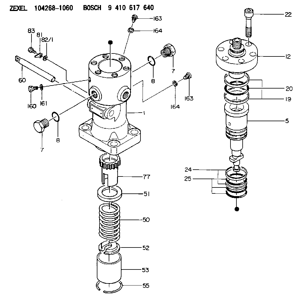
| 1. | [1] | 141054-8600 | PUMP HOUSING |
| 5. | [1] | 141187-1020 | PLUNGER-AND-BARREL ASSY |
| 7. | [2] | 141133-6301 | CAPSULE |
| 7. | [2] | 141133-6301 | CAPSULE |
| 8. | [2] | 141485-1201 | O-RING |
| 8. | [2] | 141485-1201 | O-RING |
| 12. | [1] | 141142-9520 | DELIVERY-VALVE ASSEMBLY |
| 19. | [2] | 016421-0700 | BACKUP RING |
| 20. | [1] | 141118-3000 | O-RING |
| 22. | [6] | 141124-4200 | BLEEDER SCREW |
| 24. | [2] | 016421-0600 | BACKUP RING |
| 25. | [3] | 141485-1000 | O-RING |
| 50. | [1] | 141215-7401 | COMPRESSION SPRING |
| 51. | [1] | 141216-5100 | SLOTTED WASHER |
| 52. | [1] | 141217-8300 | SLOTTED WASHER |
| 53. | [1] | 141218-9000 | GUIDE |
| 55. | [1] | 141220-2900 | LOCKING WASHER |
| 60. | [1] | 141291-1500 | CONTROL RACK |
| 77. | [1] | 141292-0400 | CONTROL SLEEVE |
| 81. | [1] | 141245-2000 | POINTER |
| 82/1. | [0] | 023500-6210 | PLAIN WASHER D11&6.4T1.5 |
| 82/1. | [0] | 029300-6010 | PLAIN WASHER D11&6.4T0.8 |
| 82/1. | [0] | 029300-6020 | PLAIN WASHER D11&6.4T0.35 |
| 83. | [1] | 020006-1440 | BLEEDER SCREW M6P1L14 |
| 160. | [1] | 141418-2600 | SET OF NUTS |
| 161. | [1] | 141403-2000 | GASKET |
| 163. | [2] | 373658-1400 | CAPSULE |
| 163. | [2] | 373658-1400 | CAPSULE |
| 164. | [2] | 141403-1800 | GASKET |
| 164. | [2] | 141403-1800 | GASKET |
Include in #2:
104268-1060
as INJECTION-PUMP ASSEMBLY
Cross reference number
Zexel num
Bosch num
Firm num
Name
104268-1060
9 410 617 640
E326470090ZZ DAIHATSU
FUEL-INJECTION PUMP
* K
* K
104268-1060
9 410 617 640
E326470090AZ DAIHATSU
FUEL-INJECTION PUMP
A * K
A * K
Information:
Machine Preparation
Prepare the machine for maintenance.Refer to Operation and Maintenance Manual, SEBU8491, "Prepare the Machine for Maintenance".Removal Procedure
Illustration 2 g06215589
(A) 383-2040 Guard
(B) 8T-4195 Bolt
(C) 8T-4121 Hard Washer
(D) 384-0966 Insert
Remove and save the DEF guard (A), three bolts (B), three hard washers (C), and three inserts (D).
Illustration 3 g06217988
(C) 8T-4121 Hard Washer
(E) 368-4513 Side Plate
(F) 365-2227 Hose As
(G) 8T-4136 Bolt
(H) 1S-0994 Clip
(J) 8T-4137 Bolt
(K) 1S-1015 Clip
(L) 7K-1181 Cable Strap
Illustration 4 g06217851
(E) 368-4513 Side Plate
Illustration 5 g06219874
View of Area M
(C) 8T-4121 Hard Washer
(H) 1S-0994 Clip
(N) 399-3078 Machine Software Gp
(P) 434-1305 Insulation
(R) 326-4516 Cable Tie
(S) 8T-4195 Bolt
(T) 7X-7729 Washer
(U) 8T-4133 Nut
Remove six hard washers (C), two bolts (G), five clips (H), two bolts (J), clip (K), four cable straps (L), five cable ties (R), protective insulation (P), two bolts (S), two washers (T), and two nuts (U) from the hose assembly (F). Discard five clips (H), clip (K), five cable ties (R). Retain the rest of the parts.
Remove and discard hose assembly (F) from DEF tank and DEF Injector Mounting Gp (N). Refer to Illustration 3 and Illustration 5.Installation Procedure
Illustration 6 g06215872
(C) 8T-4121 Hard Washer
(G) 8T-4136 Bolt
(J) 8T-4137 Bolt
(1) 471-4171 Hose As
(2) 1S-0994 Clip
(3) 7K-1181 Cable Strap
(4) 1S-1015 Clip
Illustration 7 g06219875
View of Area M
(C) 8T-4121 Hard Washer
(N) 399-6078 DEF Injector & Mounting Gp
(P) 434-1305 Insulation
(S) 8T-4195 Bolt
(T) 7X-7729 Washer
(U) 8T-4133 Nut
(1) 471-4171 Hose As
(2) 1S-0994 Clip
(5) 326-4516 Cable Tie
Install new hose assembly (1) to the DEF tank and DEF injector mounting group (N). Secure hose assembly (1) using five clips (2), four cable straps (3), clip (4), six hard washers (C), two bolts (G), two bolts (J), two bolts (S), two washers (T), and two nuts (U) that were saved in Step 2 of Section "Removal Procedure". Refer to Illustration 6 and Illustration 7.
Secure protective insulation (P) that was saved in Step 2 of Section "Removal Procedure" to hose assembly (1) using five cable ties (5). Refer to Illustration 7.
Illustration 8 g06215593
(A) 383-2040 Guard
(V) Template
Illustration 9 g06215595
(X) 94.4 mm (3.72 inch)
(Y) 225 mm (8.9 inch)
Use Illustration 9 as a template and position the template onto guard (A), aligning to the edges. Trim the guard (A) according to the template. Refer to Illustration 8.Note: Lay the template flat on the guard. The trimmed area of the guard (A) is the curved area. The square cutout on the template is not to be cut, the square corner allows the template to lay flatter on the guard.
Illustration 10 g06215889
(A) 383-2040 Guard
(E) 368-4513 Side Plate
(1) 471-4171 Hose As
Install the modified DEF guard (A) using the hardware that was saved in Step 1 of Section "Removal Procedure".Note: Ensure adequate clearance has been obtained.
Return machine to service.
Have questions with 104268-1060?
Group cross 104268-1060 ZEXEL
Daihatsu
Daihatsu
104268-1060
9 410 617 640
E326470090ZZ
FUEL-INJECTION PUMP
104268-1060
9 410 617 640
E326470090AZ
FUEL-INJECTION PUMP