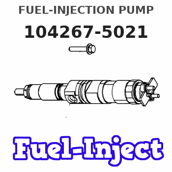
Information fuel-injection pump
BOSCH
9 410 617 851
9410617851
ZEXEL
104267-5021
1042675021

Rating:
Components :
| 0. | INJECTION-PUMP ASSEMBLY | 104267-5021 |
| 1. | _ | |
| 2. | FUEL INJECTION PUMP | |
| 3. | NUMBER PLATE | |
| 4. | _ | |
| 5. | CAPSULE | |
| 6. | ADJUSTING DEVICE | |
| 7. | NOZZLE AND HOLDER ASSY | |
| 8. | Nozzle and Holder | |
| 9. | Open Pre:MPa(Kqf/cm2) | |
| 10. | NOZZLE-HOLDER | |
| 11. | NOZZLE |
Scheme ###:
| 1. | [1] | 141053-3420 | PUMP HOUSING |
| 5. | [1] | 141176-4420 | PLUNGER-AND-BARREL ASSY |
| 7. | [2] | 141133-0500 | CAPSULE |
| 7. | [2] | 141133-0500 | CAPSULE |
| 8. | [2] | 141403-0400 | GASKET |
| 8. | [2] | 141403-0400 | GASKET |
| 12. | [1] | 141142-4920 | DELIVERY-VALVE ASSEMBLY |
| 20. | [1] | 141118-2000 | O-RING |
| 21. | [1] | 141119-3600 | FLANGE BUSHING |
| 22. | [6] | 141124-1300 | BLEEDER SCREW |
| 25. | [1] | 141482-9600 | O-RING |
| 50. | [1] | 141215-5402 | COMPRESSION SPRING |
| 51. | [1] | 141216-1800 | SLOTTED WASHER |
| 52. | [1] | 141217-5500 | SLOTTED WASHER |
| 53. | [1] | 141218-7920 | GUIDE |
| 55. | [1] | 141220-1200 | LOCKING WASHER |
| 60. | [1] | 141244-6200 | CONTROL RACK |
| 77. | [1] | 141241-7200 | CONTROL SLEEVE |
| 81. | [1] | 141245-2000 | POINTER |
| 82/1. | [0] | 023500-6210 | PLAIN WASHER D11&6.4T1.5 |
| 82/1. | [0] | 029300-6010 | PLAIN WASHER D11&6.4T0.8 |
| 82/1. | [0] | 029300-6020 | PLAIN WASHER D11&6.4T0.35 |
| 83. | [1] | 020006-1440 | BLEEDER SCREW M6P1L14 |
| 110. | [1] | 140420-1600 | BLEEDER SCREW |
| 111. | [1] | 141421-0000 | GASKET |
| 153. | [1] | 029112-6020 | CAPSULE |
| 154. | [1] | 141403-0600 | GASKET |
| 160. | [1] | 141418-1400 | SET OF NUTS |
| 161. | [1] | 141107-0700 | GASKET |
| 162. | [1] | 141480-0900 | COVER |
| 163. | [1] | 010038-1020 | BLEEDER SCREW |
| 164. | [1] | 141107-0700 | GASKET |
Cross reference number
Zexel num
Bosch num
Firm num
Name
104267-5021
FUEL-INJECTION PUMP
K 24FX FUEL INJECTION PUMP PF-1GX PF
K 24FX FUEL INJECTION PUMP PF-1GX PF
Information:
Introduction
The problem that is identified below does not have a known permanent solution. Until a permanent solution is known, use the solution that is identified below.Problem
If the engine is stored for 6 months or more, the fuel injection pump linkage needs to be lubricated.Solution
Follow the procedure in this article to lubricate the fuel injection pump linkage.
Remove the fuel shutoff solenoid. Refer to Disassembly and Assembly, "Fuel Shutoff Solenoid - Remove and Install" for the correct procedure.
Spray the fuel control rack with a suitable lubricant spray.
Use a suitable magnet to operate the fuel control rack. The operation of the fuel control rack will disperse the lubricant.Note: If the fuel control rack does not move freely, then the fuel injection pump should be replaced. Refer to Disassembly and Assembly, "Fuel Injection Pump - Remove and Install" for the correct procedure.
Install the fuel shutoff solenoid. Refer to Disassembly and Assembly, "Fuel Shutoff Solenoid - Remove and Install" for the correct procedure.
Record the repair in the Service Information Management System (SIMSi), including the engine/machine serial number and the date of the repair.
