Information fuel-injection pump
BOSCH
9 410 618 342
9410618342
ZEXEL
104266-1210
1042661210
DAIHATSU
E286470200BZ
e286470200bz

Rating:
Components :
| 0. | INJECTION-PUMP ASSEMBLY | 104266-1210 |
| 1. | _ | |
| 2. | FUEL INJECTION PUMP | |
| 3. | NUMBER PLATE | |
| 4. | _ | |
| 5. | CAPSULE | |
| 6. | ADJUSTING DEVICE | |
| 7. | NOZZLE AND HOLDER ASSY | |
| 8. | Nozzle and Holder | |
| 9. | Open Pre:MPa(Kqf/cm2) | |
| 10. | NOZZLE-HOLDER | |
| 11. | NOZZLE |
Scheme ###:
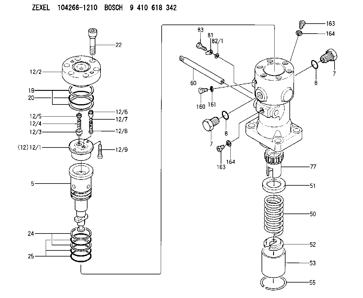
| 5. | [1] | 141187-3720 | PLUNGER-AND-BARREL ASSY |
| 7. | [2] | 141133-6901 | CAPSULE |
| 7. | [2] | 141133-6901 | CAPSULE |
| 8. | [2] | 141485-1203 | O-RING |
| 8. | [2] | 141485-1203 | O-RING |
| 12. | [1] | 141145-4021 | DELIVERY-VALVE ASSEMBLY |
| 12/1. | [1] | 141146-1800 | SEAT;D.V. |
| 12/2. | [1] | 141138-0500 | FITTING |
| 12/3. | [1] | 141142-9100 | VALVE BODY |
| 12/4. | [1] | 141144-0500 | COMPRESSION SPRING |
| 12/5. | [1] | 141113-3201 | SLOTTED WASHER |
| 12/6. | [1] | 141145-8400 | VALVE BODY |
| 12/7. | [1] | 141112-8701 | COILED SPRING |
| 12/8. | [1] | 141113-2003 | FILLER PIECE |
| 12/9. | [2] | 010235-1620 | HEX-SOCKET-HEAD CAP SCREW |
| 19. | [2] | 016421-0700 | BACKUP RING |
| 20. | [1] | 141118-3002 | O-RING |
| 22. | [6] | 141124-4200 | BLEEDER SCREW |
| 24. | [2] | 016421-0600 | BACKUP RING |
| 25. | [3] | 141485-1002 | O-RING |
| 50. | [1] | 141215-7401 | COMPRESSION SPRING |
| 51. | [1] | 141216-5100 | SLOTTED WASHER |
| 52. | [1] | 141217-8300 | SLOTTED WASHER |
| 53. | [1] | 141218-9000 | GUIDE |
| 55. | [1] | 141220-2900 | LOCKING WASHER |
| 60. | [1] | 141291-1500 | CONTROL RACK |
| 77. | [1] | 141292-5400 | CONTROL SLEEVE |
| 81. | [1] | 141245-2000 | POINTER |
| 82/1. | [0] | 023500-6210 | PLAIN WASHER D11&6.4T1.5 |
| 82/1. | [0] | 029300-6010 | PLAIN WASHER D11&6.4T0.8 |
| 82/1. | [0] | 029300-6020 | PLAIN WASHER D11&6.4T0.35 |
| 83. | [1] | 020006-1440 | BLEEDER SCREW M6P1L14 |
| 160. | [1] | 141418-2600 | SET OF NUTS |
| 161. | [1] | 141403-2000 | GASKET |
| 163. | [2] | 373658-1400 | CAPSULE |
| 163. | [2] | 373658-1400 | CAPSULE |
| 164. | [2] | 141403-1800 | GASKET |
| 164. | [2] | 141403-1800 | GASKET |
Include in #1:
101491-9640
as _
Include in #2:
104266-1210
as INJECTION-PUMP ASSEMBLY
Cross reference number
Zexel num
Bosch num
Firm num
Name
104266-1210
E286470200BZ DAIHATSU
FUEL-INJECTION PUMP
K 24FW FUEL INJECTION PUMP PF-1SV PF
K 24FW FUEL INJECTION PUMP PF-1SV PF
Information:
Introduction
Do not perform any procedure in this Special Instruction until you have read this information and you understand this information.Required Parts
Table 1
Required Parts
Item Qty New Part Number Part Name
1 2 137-8101 O-Ring Seal
2 2 286-5030 Elbow
3 1 289-3891 Clip
4 1 294-6118 Pressure Sensor
5 1 356-0920 Bracket
6 2 3J-7352 Connector
7 2 6V-5048 O-Ring Seal
8 2 8T-0267 Bolt
9 2 9X-8267 Washer
10 108-9656 Cable Straps
11 2 5P-1717 Hose Clamp
12 1 356-6802 Sensor Harness As
13 1 289-3891 Clip
14 2 5P-3860 Hose Clamp Procedure
Illustration 1 g02082554
Example of a vertical filter group (1) Connection for the pressure sensor group (2) New bypass wiring harness (3) Connection for the mounted sensor group (4) OEM wiring harness connection (5) OEM wiring harness (6) Wire for the probe of the outlet temperature is secured to the new P1 tube. (7) Support bracket for the new P1 tube (8) New P1 tube (9) The wire for the probe for the inlet temperature is secured to new P1 tube. (10) New P2 tubeNote: Avoid placing