Information fuel-injection pump
BOSCH
9 410 617 634
9410617634
ZEXEL
104266-1081
1042661081
DAIHATSU
E286470020ZZ
e286470020zz

Rating:
Components :
| 0. | INJECTION-PUMP ASSEMBLY | 104266-1081 |
| 1. | _ | |
| 2. | FUEL INJECTION PUMP | |
| 3. | NUMBER PLATE | |
| 4. | _ | |
| 5. | CAPSULE | |
| 6. | ADJUSTING DEVICE | |
| 7. | NOZZLE AND HOLDER ASSY | |
| 8. | Nozzle and Holder | |
| 9. | Open Pre:MPa(Kqf/cm2) | |
| 10. | NOZZLE-HOLDER | |
| 11. | NOZZLE | 105012-4370 |
Scheme ###:
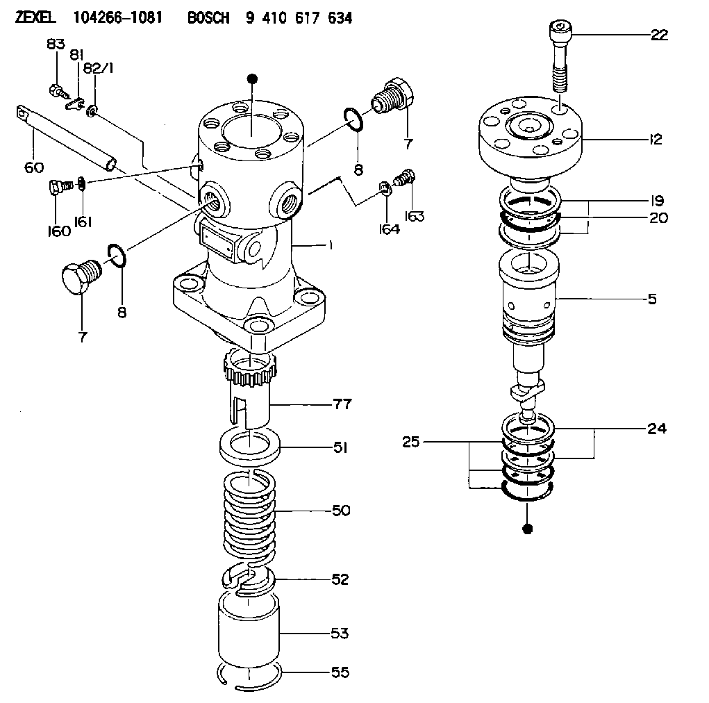
| 1. | [1] | 141055-4000 | PUMP HOUSING |
| 5. | [1] | 141187-1821 | PLUNGER-AND-BARREL ASSY |
| 7. | [2] | 141133-6900 | CAPSULE |
| 7. | [2] | 141133-6900 | CAPSULE |
| 8. | [2] | 141485-1201 | O-RING |
| 8. | [2] | 141485-1201 | O-RING |
| 12. | [1] | 141145-4020 | DELIVERY-VALVE ASSEMBLY |
| 19. | [2] | 016421-0700 | BACKUP RING |
| 20. | [1] | 141118-3000 | O-RING |
| 22. | [6] | 141124-4200 | BLEEDER SCREW |
| 24. | [2] | 016421-0600 | BACKUP RING |
| 25. | [3] | 141485-1000 | O-RING |
| 50. | [1] | 141215-7401 | COMPRESSION SPRING |
| 51. | [1] | 141216-5100 | SLOTTED WASHER |
| 52. | [1] | 141217-8300 | SLOTTED WASHER |
| 53. | [1] | 141218-9000 | GUIDE |
| 55. | [1] | 141220-2900 | LOCKING WASHER |
| 60. | [1] | 141291-1500 | CONTROL RACK |
| 77. | [1] | 141292-2000 | CONTROL SLEEVE |
| 81. | [1] | 141245-2000 | POINTER |
| 82/1. | [0] | 023500-6210 | PLAIN WASHER D11&6.4T1.5 |
| 82/1. | [0] | 029300-6010 | PLAIN WASHER D11&6.4T0.8 |
| 82/1. | [0] | 029300-6020 | PLAIN WASHER D11&6.4T0.35 |
| 83. | [1] | 020006-1440 | BLEEDER SCREW M6P1L14 |
| 160. | [1] | 141418-2600 | SET OF NUTS |
| 161. | [1] | 141403-2000 | GASKET |
| 163. | [2] | 373658-1400 | CAPSULE |
| 164. | [2] | 141403-1800 | GASKET |
Include in #1:
101491-9680
as _
Include in #2:
104266-1081
as INJECTION-PUMP ASSEMBLY
Cross reference number
Zexel num
Bosch num
Firm num
Name
Information:
Do not operate or work on this product unless you have read and understood the instruction and warnings in the relevant Operation and Maintenance Manuals and relevant service literature. Failure to follow the instructions or heed the warnings could result in injury or death. Proper care is your responsibility.
The new and former rocker arm base assembly is listed in Table 1.Note: The 568-8215 Rocker Arm Base As has the following serviceable components.
Table 1
Required Parts
Qty New Part Number Part Name Former Part Number(1)
1 568-8215 Rocker Arm Base As 121-2024
2 261-0195 Hollow Dowel 8N-4387
1 567-2901 Spacer N/A
1 567-2902 Spacer N/A
3 6V-6228 O-Ring Seal N/A
1 240-7032 Seal N/A
(1) The former part number listed is for reference only and may differ.
Illustration 1 g06562147
(1) 567-2901 Spacer
(2) 6V-6228 O-Ring Seal
(3) 567-2902 Spacer
Illustration 2 g06562161
(4) 240-7032 Seal
(5) 261-0195 Hollow Dowel
Illustration 3 g06562155
(6) 568-8215 Rocker Arm Base As
(7) 121-2024 Base AsNote: Refer to the Illustration 3 to see the differences between the new and former designs.