Information fuel-injection pump
BOSCH
9 410 617 909
9410617909
ZEXEL
104265-3020
1042653020
Rating:
Components :
| 0. | INJECTION-PUMP ASSEMBLY | 104265-3020 |
| 1. | _ | |
| 2. | FUEL INJECTION PUMP | |
| 3. | NUMBER PLATE | |
| 4. | _ | |
| 5. | CAPSULE | |
| 6. | ADJUSTING DEVICE | |
| 7. | NOZZLE AND HOLDER ASSY | |
| 8. | Nozzle and Holder | |
| 9. | Open Pre:MPa(Kqf/cm2) | 27.5{280} |
| 10. | NOZZLE-HOLDER | |
| 11. | NOZZLE | 105012-4370 |
Scheme ###:
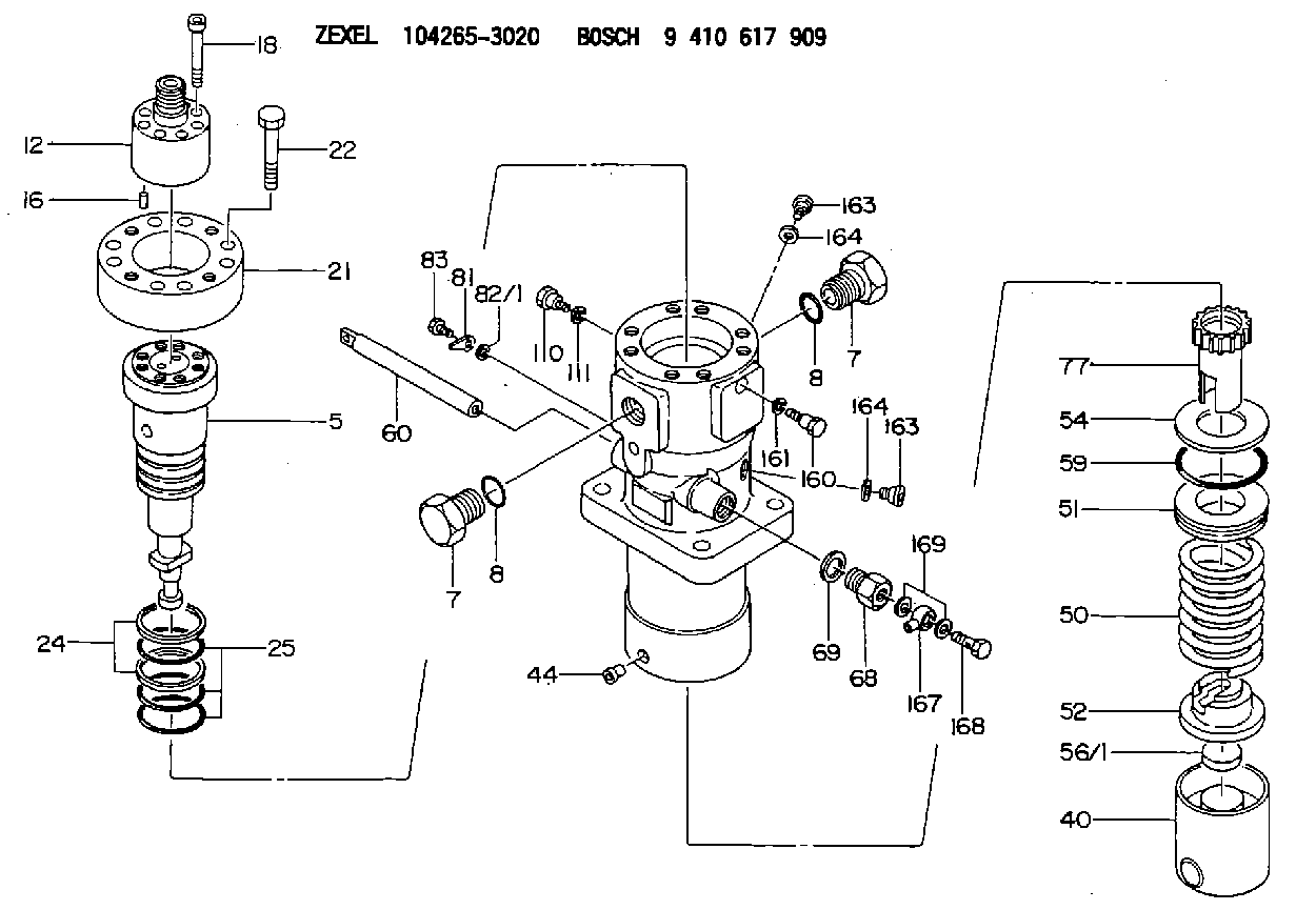
| 5. | [1] | 141189-5320 | PLUNGER-AND-BARREL ASSY |
| 7. | [2] | 141133-9200 | CAPSULE |
| 7. | [2] | 141133-9200 | CAPSULE |
| 8. | [2] | 141485-1302 | O-RING |
| 8. | [2] | 141485-1302 | O-RING |
| 12. | [1] | 141145-6520 | DELIVERY-VALVE ASSEMBLY |
| 16. | [1] | 150508-3100 | BEARING PIN |
| 18. | [8] | 141124-5900 | HEX-SOCKET-HEAD CAP SCREW |
| 21. | [1] | 141119-4901 | FLANGE BUSHING |
| 22. | [8] | 141124-6000 | BLEEDER SCREW |
| 24. | [2] | 016421-0600 | BACKUP RING |
| 25. | [3] | 141485-1002 | O-RING |
| 40. | [1] | 141200-3521 | TAPPET |
| 44. | [1] | 141212-0300 | BEARING PIN |
| 50. | [1] | 141215-9000 | COMPRESSION SPRING |
| 51. | [1] | 141216-7120 | SLOTTED WASHER |
| 52. | [1] | 141217-9600 | SLOTTED WASHER |
| 54. | [1] | 141450-2100 | PLATE |
| 56/1. | [1] | 141209-5000 | PLATE |
| 56/1. | [1] | 141209-5100 | PLATE |
| 56/1. | [1] | 141209-5200 | PLATE |
| 56/1. | [1] | 141209-5300 | PLATE |
| 56/1. | [1] | 141209-5400 | PLATE |
| 56/1. | [1] | 141209-5500 | PLATE |
| 56/1. | [1] | 141209-5600 | PLATE |
| 59. | [1] | 141485-0602 | O-RING |
| 60. | [1] | 141291-5200 | CONTROL RACK |
| 68. | [1] | 141405-4900 | ADAPTOR |
| 69. | [1] | 026520-2440 | GASKET D23.9&20.2T1 |
| 77. | [1] | 141292-3700 | CONTROL SLEEVE |
| 81. | [1] | 141245-2000 | POINTER |
| 82/1. | [0] | 023500-6210 | PLAIN WASHER D11&6.4T1.5 |
| 82/1. | [0] | 029300-6010 | PLAIN WASHER D11&6.4T0.8 |
| 82/1. | [0] | 029300-6020 | PLAIN WASHER D11&6.4T0.35 |
| 83. | [1] | 020006-1440 | BLEEDER SCREW M6P1L14 |
| 110. | [1] | 141418-2600 | SET OF NUTS |
| 111. | [1] | 141403-2000 | GASKET |
| 160. | [1] | 141418-2600 | SET OF NUTS |
| 161. | [1] | 141403-2000 | GASKET |
| 163. | [2] | 373658-1400 | CAPSULE |
| 163. | [2] | 373658-1400 | CAPSULE |
| 164. | [2] | 141403-1800 | GASKET |
| 164. | [2] | 141403-1800 | GASKET |
| 167. | [1] | 150948-0000 | INLET UNION |
| 168. | [1] | 150949-0100 | EYE BOLT |
| 169. | [2] | 150521-0800 | GASKET |
Include in #2:
104265-3020
as INJECTION-PUMP ASSEMBLY
Cross reference number
Zexel num
Bosch num
Firm num
Name
Information:
Table 1
Required Parts
Item Qty Part Number Description Former Part Number
1 1 560-4252 Bracket 431-8663
2 1 396-3862 (1) Control Harness As 396-3862 (1)
524-5527 (2) Control Harness As 524-5527 (2)
3 1 471-4176 Hose As 380-9241
4 - 7K-1181 Cable Strap NA
5 - 3E-6909 Clip NA
(1) FMC 1 - 772 (Not Equipped with DEF Quality Sensor)
(2) FMC 773 - Up (Equipped with DEF Quality Sensor)Note: These parts should be ordered and replaced only if there is evidence of damage to any part.Rework Procedure
Park the machine on level ground, lower all implements to the ground, shut off machine, and relieve all hydraulic system pressure.
Read and understand this Rework Procedure before starting work.
Illustration 1 g06340431
General location and reference Views
DEF tank cover not shown for clarity.
(A) Fuel tank
(B) Diesel Exhaust Fluid (DEF) module group
See Illustration for the general location of the DEF Module Group and reference views that will be used in future steps.
Illustration 2 g06340436
Location of hardware.
(C) Hardware
(D) DEF fill hose
(E) Clamp
Inspect control harness assembly (2) at location (AA) and hose assembly (3) at location (BB) for rubbing and or fouling on the DEF Tank Cover. If either item is damaged, replace the damaged part.Note: Hardware (C) holding the DEF Module Group to the fuel tank and clamp (E) holding DEF Fill Hose (D) to the tank will need to be loosened to reposition the DEF Module Group to access control harness assembly (2) and hose assembly (3).
After control harness assembly (2) and hose assembly (3) have been inspected and found without damage OR replaced, secure both parts using Steps 6 through 9.
Illustration 3 g06340441
Left view
Fuel tank not shown.
(F) Diesel exhaust fluid module
Illustration 4 g06340446
Location CC
(G) Harness bundled to avoid fouling
Illustration 5 g06340447
Location DD
(H) Terminating resistor
Secure control harness assembly (2) and hose assembly (3) to left side of DEF Module using tie straps (4).Reference: Refer to Illustrations 3, 4, and 5.Note: At location (CC), use tie straps to secure harness bundles to prevent harness from contacting the fuel tank. (See Illustration 4).Note: At location (DD), use tie straps (4) to secure control harness assembly (2) and hose assembly (3), and terminating resistor (H) at lower location. (See Illustration 5).
Illustration 6 g06340448
Location of hardware
(C) Hardware
(E) Clamp
Reposition the DEF Module Group, install bracket (1), and reinstall the remaining hardware (C), clamp (E) removed in Step 4. Check to make sure control harness assembly (2) and hose assembly (3) will not