Information fuel-injection pump
BOSCH
9 410 617 615
9410617615
ZEXEL
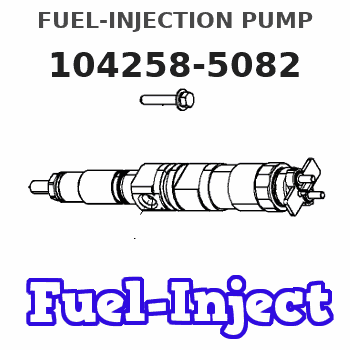
104258-5082
1042585082
DAIHATSU
E286450030BA
e286450030ba
Rating:
Components :
| 0. | INJECTION-PUMP ASSEMBLY | 104258-5082 |
| 1. | _ | |
| 2. | FUEL INJECTION PUMP | |
| 3. | NUMBER PLATE | |
| 4. | _ | |
| 5. | CAPSULE | |
| 6. | ADJUSTING DEVICE | |
| 7. | NOZZLE AND HOLDER ASSY | |
| 8. | Nozzle and Holder | |
| 9. | Open Pre:MPa(Kqf/cm2) | |
| 10. | NOZZLE-HOLDER | |
| 11. | NOZZLE |
Scheme ###:
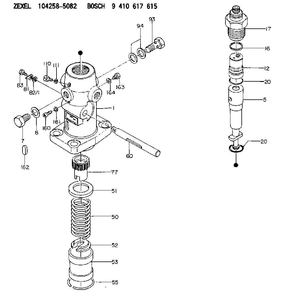
| 1. | [1] | 141053-9300 | PUMP HOUSING |
| 5. | [1] | 141175-8720 | PLUNGER-AND-BARREL ASSY |
| 7. | [1] | 141133-0200 | CAPSULE |
| 8. | [1] | 141403-1100 | GASKET |
| 12. | [1] | 141142-5821 | DELIVERY-VALVE ASSEMBLY |
| 16. | [1] | 141115-6000 | GASKET |
| 17. | [1] | 141136-7700 | FITTING |
| 20. | [2] | 141118-1900 | O-RING |
| 20. | [2] | 141118-1900 | O-RING |
| 50. | [1] | 141215-5001 | COMPRESSION SPRING |
| 51. | [1] | 141216-0100 | SLOTTED WASHER |
| 52. | [1] | 141217-5100 | SLOTTED WASHER |
| 53. | [1] | 141218-7700 | GUIDE |
| 55. | [1] | 026110-6010 | LOCKING WASHER |
| 60. | [1] | 141244-4300 | CONTROL RACK |
| 77. | [1] | 141241-6600 | CONTROL SLEEVE |
| 81. | [1] | 141245-2000 | POINTER |
| 82/1. | [0] | 023500-6210 | PLAIN WASHER D11&6.4T1.5 |
| 82/1. | [0] | 029300-6010 | PLAIN WASHER D11&6.4T0.8 |
| 82/1. | [0] | 029300-6020 | PLAIN WASHER D11&6.4T0.35 |
| 83. | [1] | 020006-1440 | BLEEDER SCREW M6P1L14 |
| 93. | [1] | 141402-3320 | EYE BOLT |
| 94. | [2] | 141403-1700 | GASKET |
| 110. | [1] | 140420-1600 | BLEEDER SCREW |
| 111. | [1] | 141403-1200 | GASKET |
| 160. | [1] | 141418-1100 | SET OF NUTS |
| 161. | [1] | 026506-1040 | GASKET D9.9&6.2T1 |
| 162. | [1] | 141480-0700 | COVER |
| 163. | [1] | 029111-0010 | CAPSULE |
| 164. | [1] | 026510-1340 | GASKET D13.4&10.2T1 |
Cross reference number
Zexel num
Bosch num
Firm num
Name
104258-5082
E286450030BA DAIHATSU
FUEL-INJECTION PUMP
K 24EX FUEL INJECTION PUMP PF-1WX PF
K 24EX FUEL INJECTION PUMP PF-1WX PF
Information:
Tools that are Required for Installation
Table 2
Required Tools
Tool Part Number Part Description Qty
B 9U-6862 Tapered Brush 1
9U-6863 Small Bore Brush 1
9U-7244 End Brush 1
9U-7237 Brush Extension 1
4C-5552 Large Bore Brush 1
C (1) 221-9778 Puller Stud 1
D (1) 9U-7258 Driver Cap 1
E 4C-9507 Retaining Compound -
( 1 ) Part of the 9U-6891 Injector Tool Group Removal Procedure
Keep all parts clean from contaminants.Contaminants may cause rapid wear and shortened component life.
Remove the electronic unit injector. Refer to Disassembly and Assembly, "Electronic Unit Injector - Remove".
Illustration 1 g01016237
Install the puller stud from Tooling (A) into unit injector sleeve (1) .
Install the following parts from Tooling (A) over the stud: bridge puller, thrust bearing, hard washer and nut.
Tighten the nut until unit injector sleeve (1) is pulled free of the cylinder head assembly.Installation Procedure
Use Tooling (B) to clean the bore in the cylinder head for the electronic unit injector sleeve.
Ensure that the electronic unit injector sleeve and the cylinder head bore are completely free of oil, dirt, and sealant debris.
Illustration 2 g01120522
Install new O-ring seals (2) on electronic unit injector sleeve (1) .Note: Do not apply Tooling (E) to the cylinder head surfaces. Apply Tooling (E) on the electronic unit injector sleeve only.
Apply Tooling (E) to the contact surface of electronic unit injector sleeve (1) on the surface that is marked "X".
Lubricate O-ring seals (2) with clean engine oil.
Illustration 3 g01076119
Install Tooling (C) into the threads of electronic unit injector sleeve (1) .
Position Tooling (C) and the electronic unit injector sleeve in the cylinder head. Use care not to damage the O-ring seal on the electronic unit injector sleeve.
Use Tooling (D) and a hammer to install electronic unit injector sleeve (1) in the cylinder head.
Ensure that the electronic unit injector sleeve is properly seated in the cylinder head. The Tooling will "RING" when the electronic unit injector sleeve is fully seated in the bore of the cylinder head.
Remove Tooling (D) and Tooling (C). Use a clean towel and remove excess Tooling (E) .
Install the electronic unit injector. Refer to Disassembly and Assembly, "Electronic Unit Injector - Install".
Fill the cooling system with coolant. Refer to Operation and Maintenance, "Refill Capacities" for the cooling system capacity.