Information fuel-injection pump
BOSCH
9 410 618 430
9410618430
ZEXEL
104258-3001
1042583001
NIIGATA-TEKKOU
7BG47010B
7bg47010b
Rating:
Components :
| 0. | INJECTION-PUMP ASSEMBLY | 104258-3001 |
| 1. | _ | |
| 2. | FUEL INJECTION PUMP | |
| 3. | NUMBER PLATE | |
| 4. | _ | |
| 5. | CAPSULE | |
| 6. | ADJUSTING DEVICE | |
| 7. | NOZZLE AND HOLDER ASSY | |
| 8. | Nozzle and Holder | |
| 9. | Open Pre:MPa(Kqf/cm2) | |
| 10. | NOZZLE-HOLDER | |
| 11. | NOZZLE |
Scheme ###:
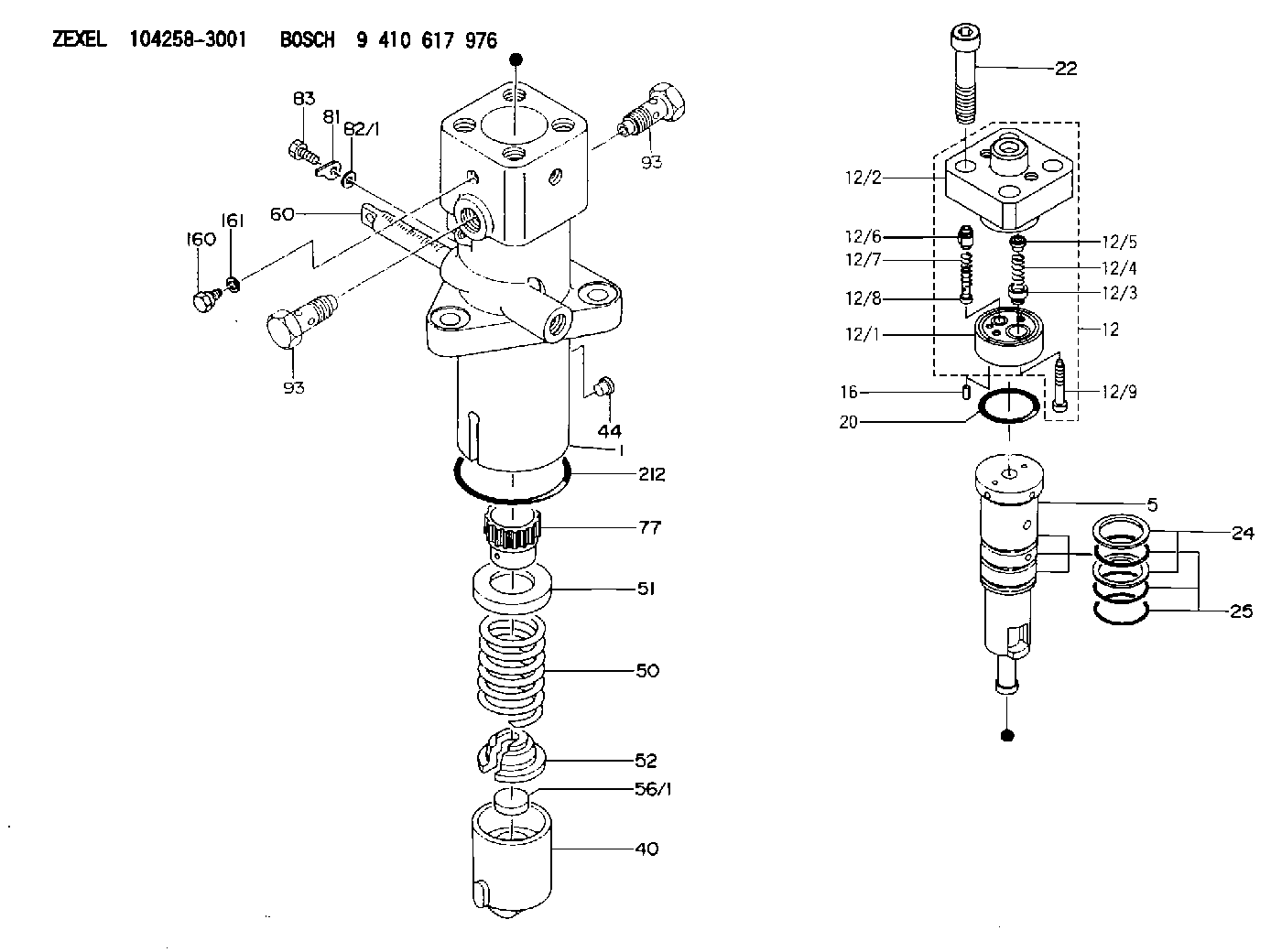
| 5. | [1] | 141189-0720 | PLUNGER-AND-BARREL ASSY WS19 |
| 12. | [1] | 141145-8320 | DELIVERY-VALVE ASSEMBLY WS4 |
| 12/1. | [1] | 141146-2700 | SEAT;D.V |
| 12/2. | [1] | 141138-3700 | FITTING |
| 12/3. | [1] | 141142-9700 | VALVE BODY |
| 12/4. | [1] | 141144-0600 | COMPRESSION SPRING |
| 12/5. | [1] | 141113-3700 | SLOTTED WASHER |
| 12/6. | [1] | 141145-8100 | VALVE BODY |
| 12/7. | [1] | 141144-1400 | COMPRESSION SPRING |
| 12/8. | [1] | 141113-4800 | FILLER PIECE |
| 12/9. | [2] | 010233-2020 | HEX-SOCKET-HEAD CAP SCREW |
| 16. | [1] | 015204-0100 | SPRING PIN |
| 20. | [1] | 141485-1002 | O-RING |
| 22. | [4] | 141269-1500 | BLEEDER SCREW |
| 24. | [2] | 016420-0400 | BACKUP RING |
| 25. | [3] | 141485-6800 | O-RING |
| 40. | [1] | 141200-3821 | TAPPET |
| 44. | [1] | 141212-0500 | BEARING PIN |
| 50. | [1] | 141215-8500 | COMPRESSION SPRING |
| 51. | [1] | 141216-6801 | SLOTTED WASHER |
| 52. | [1] | 141217-9101 | SLOTTED WASHER |
| 56/1. | [1] | 141209-2400 | PLATE T7.6 |
| 56/1. | [1] | 141209-2500 | PLATE T7.7 |
| 56/1. | [1] | 141209-2600 | PLATE T7.8 |
| 56/1. | [1] | 141209-2700 | PLATE T7.9 |
| 56/1. | [1] | 141209-2800 | PLATE T8.0 |
| 56/1. | [1] | 141209-2900 | PLATE T8.1 |
| 56/1. | [1] | 141209-3000 | PLATE T8.2 |
| 56/1. | [1] | 141209-3100 | PLATE T8.3 |
| 56/1. | [1] | 141209-3200 | PLATE T8.4 |
| 56/1. | [1] | 141209-3300 | PLATE T8.5 |
| 56/1. | [1] | 141209-3400 | PLATE T8.6 |
| 56/1. | [1] | 141209-3500 | PLATE T8.7 |
| 56/1. | [1] | 141209-3600 | PLATE T8.8 |
| 56/1. | [1] | 141209-3700 | PLATE T8.9 |
| 56/1. | [1] | 141209-3800 | PLATE T9.0 |
| 60. | [1] | 141291-6000 | CONTROL RACK |
| 77. | [1] | 141292-5000 | CONTROL SLEEVE |
| 81. | [1] | 141245-2000 | POINTER |
| 82/1. | [0] | 023500-6210 | PLAIN WASHER D11&6.4T1.5 |
| 82/1. | [0] | 029300-6010 | PLAIN WASHER D11&6.4T0.8 |
| 82/1. | [0] | 029300-6020 | PLAIN WASHER D11&6.4T0.35 |
| 83. | [1] | 020006-1440 | BLEEDER SCREW |
| 93. | [2] | 141402-7301 | EYE BOLT |
| 93. | [2] | 141402-7301 | EYE BOLT |
| 160. | [1] | 141418-2200 | SET OF NUTS |
| 161. | [1] | 141403-1400 | GASKET |
| 212. | [1] | 016510-8550 | O-RING |
Cross reference number
Zexel num
Bosch num
Firm num
Name
104258-3001
7BG47010B NIIGATA-TEKKOU
FUEL-INJECTION PUMP
K 24ES FUEL INJECTION PUMP PF-R1WS PF
K 24ES FUEL INJECTION PUMP PF-R1WS PF
Information:
Illustration 1 g01068766
Inlet fuel line (fuel transfer pump to cylinder head) (1) Connector (2) Hose assembly (3) Fuel transfer pump
Remove connector (1) and hose assembly (2) from the fuel transfer pump (3). Refer to Illustration 1. Retain these parts for the reinstallation.
Illustration 2 g01068729
Outlet fuel line (fuel transfer pump to secondary fuel filter) (4) Adapter (5) Tee (6) Elbow (7) Hose assembly
Remove adapter (4), tee (5), elbow (6), and hose assembly (7) from the fuel transfer pump (3). Refer to Illustration 2. Retain these parts for the reinstallation.Note: Modifications to the tools may need to be made in order to reduce interference with engine components. Refer to Illustration 3.
Illustration 3 g01007381
Modified 2P-5494 crowfoot wrench
Illustration 4 g01068745
(3) Fuel transfer pump (8) Bolt (9) Bolt (10) Washer (11) Adapter (15) HEUI pump (21) Clip
Remove the bolt (8) and the clip (21) from the top of the fuel transfer pump. Refer to Illustration 4.
Remove the bolt (9) and the washer (10) from the bottom of the fuel transfer pump (3). Refer to Illustration 4.
Remove fuel transfer pump (3). Refer to Illustration 4.
Illustration 5 g01068776
(12) 45 ° adapter (13) Hose assembly (14) Straight connector (15) HEUI pump
Remove hose assembly (13) from 45 degree adapter (12) and straight connector (14) by using removal tool (A). Refer to Illustration 5.
Remove 45 degree adapter (12) from the HEUI pump (15). Remove straight adapter (14) from the cylinder head. Discard the parts. Refer to Illustration 5.Installation of the Engine Oil Lines Group
Illustration 6 g01068779
(16) 247-3755 Tube As (17) 6V-8636 Connector (18) 221-3494 O-Ring Seal (19) 214-7568 O-Ring Seal (20) 6V-8724 Elbow
Apply a light coat of oil to the O-rings (18) and (19) during installation. Install the O-ring (18) on