Information fuel-injection pump
BOSCH
9 410 617 976
9410617976
ZEXEL
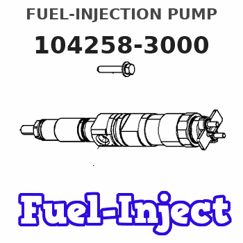
104258-3000
1042583000
NIIGATA-TEKKOU
7BG47003A
7bg47003a
Rating:
Components :
| 0. | INJECTION-PUMP ASSEMBLY | 104258-3000 |
| 1. | _ | |
| 2. | FUEL INJECTION PUMP | |
| 3. | NUMBER PLATE | |
| 4. | _ | |
| 5. | CAPSULE | |
| 6. | ADJUSTING DEVICE | |
| 7. | NOZZLE AND HOLDER ASSY | |
| 8. | Nozzle and Holder | |
| 9. | Open Pre:MPa(Kqf/cm2) | |
| 10. | NOZZLE-HOLDER | |
| 11. | NOZZLE |
Scheme ###:
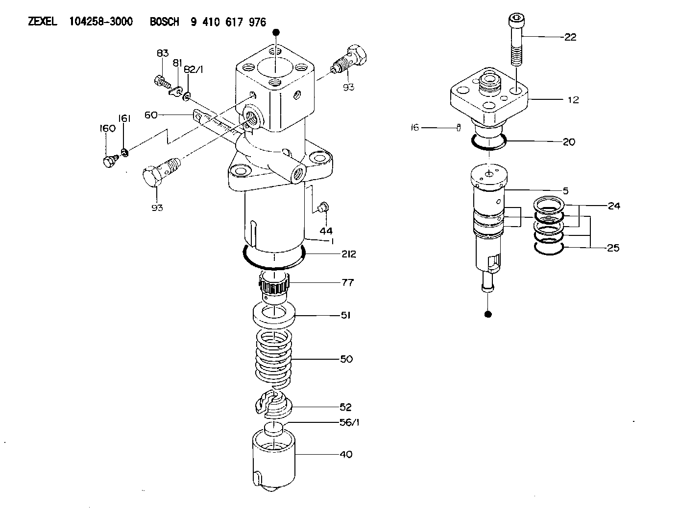
| 5. | [1] | 141189-0720 | PLUNGER-AND-BARREL ASSY |
| 12. | [1] | 141145-8320 | DELIVERY-VALVE ASSEMBLY |
| 16. | [1] | 015204-0100 | SPRING PIN |
| 20. | [1] | 141485-1002 | O-RING |
| 22. | [4] | 141269-1200 | BLEEDER SCREW |
| 24. | [2] | 016420-0400 | BACKUP RING |
| 25. | [3] | 141485-4500 | O-RING |
| 40. | [1] | 141200-3820 | TAPPET |
| 44. | [1] | 141212-0500 | BEARING PIN |
| 50. | [1] | 141215-8500 | COMPRESSION SPRING |
| 51. | [1] | 141216-6800 | SLOTTED WASHER |
| 52. | [1] | 141217-9100 | SLOTTED WASHER |
| 56/1. | [1] | 141209-2400 | PLATE T7.6 |
| 56/1. | [1] | 141209-2500 | PLATE T7.7 |
| 56/1. | [1] | 141209-2600 | PLATE T7.8 |
| 56/1. | [1] | 141209-2700 | PLATE T7.9 |
| 56/1. | [1] | 141209-2800 | PLATE T8.0 |
| 56/1. | [1] | 141209-2900 | PLATE T8.1 |
| 56/1. | [1] | 141209-3000 | PLATE T8.2 |
| 56/1. | [1] | 141209-3100 | PLATE T8.3 |
| 56/1. | [1] | 141209-3200 | PLATE T8.4 |
| 56/1. | [1] | 141209-3300 | PLATE T8.5 |
| 56/1. | [1] | 141209-3400 | PLATE T8.6 |
| 56/1. | [1] | 141209-3500 | PLATE T8.7 |
| 56/1. | [1] | 141209-3600 | PLATE T8.8 |
| 56/1. | [1] | 141209-3700 | PLATE T8.9 |
| 56/1. | [1] | 141209-3800 | PLATE T9.0 |
| 60. | [1] | 141291-6000 | CONTROL RACK |
| 77. | [1] | 141292-5000 | CONTROL SLEEVE |
| 81. | [1] | 141245-2000 | POINTER |
| 82/1. | [0] | 023500-6210 | PLAIN WASHER D11&6.4T1.5 |
| 82/1. | [0] | 029300-6010 | PLAIN WASHER D11&6.4T0.8 |
| 82/1. | [0] | 029300-6020 | PLAIN WASHER D11&6.4T0.35 |
| 83. | [1] | 020006-1440 | BLEEDER SCREW M6P1L14 |
| 93. | [2] | 141402-7301 | EYE BOLT |
| 93. | [2] | 141402-7301 | EYE BOLT |
| 160. | [1] | 141418-2200 | SET OF NUTS |
| 161. | [1] | 141403-1400 | GASKET |
| 212. | [1] | 016510-8550 | O-RING |
Cross reference number
Zexel num
Bosch num
Firm num
Name
9 410 617 976
7BG47003A NIIGATA-TEKKOU
FUEL-INJECTION PUMP
* K 24ES PF-R1WS PF
* K 24ES PF-R1WS PF
Information:
Table 1
Sales Model Adaptable to Machines Effective in Production with Machines
D3K 2 S/N:JPJ1-199 S/N:JPJ200-UP
S/N:KL21-208 S/N:KL2209-UP
S/N:LT31-113 S/N:LT3114-UP
S/N:FT31-102 S/N:FT3103-UP
S/N:KF21-174 S/N:KF2175-UP
D4K 2 S/N:KR21-203 S/N:KR2204-UP
S/N:RT31-130 S/N:RT3131-UP
S/N:KM21-196 S/N:KM2197-UP
S/N:MT31-119 S/N:MT3120-UP
D5K 2 S/N:KY21-357 S/N:KY2358-UP
S/N:RRE1-232 S/N:RRE233-UP
S/N:YT31-153 S/N:YT3154-UP
S/N:KW21-308 S/N:KW2309-UP
S/N:WT31-145 S/N:WT3146-UP In the event, the original bolt should come loose or is lost, use one of the following procedures and parts list for reworking the latch assembly.Rework Procedure
Table 2
New Parts List
Item Quantity Part Number Description
1 1 275-0571 Latch Cam
2 1 7X-2619 Bolt
3 1 9X-8256 Washer
4 1 275-0572 Latch As
Illustration 1 g06026857Procedure if the original cam latch retaining bolt is loose
Illustration 2 g06025999
Remove bolt (2), keeping cam latch (1) in position.
Apply Loctite 243 to the threads of bolt (2). Torque the bolt to 6 1 N m (53 9 lb in) using a torque wrench.Procedure if only the original cam latch bolt and cam latch are missing
Illustration 3 g06026021
Install new cam latch (1) to the latch body.
Replace missing retaining bolt with a 7X-2619 Bolt (2) and 9X-8256 Washer (3). This washer is required as the new bolt is too long and will bottom out in the latch body before tightening. Install using Loctite 243. Torque the bolt to 6 1 N m (53 9 lb in) using a torque wrench.Procedure if the original cam latch retaining bolt, cam latch and latch assembly are missing
Illustration 4 g06026825
Illustration 5 g06026826
Illustration 6 g06026831
(E) Side 1 of Retaining Nut
(F) Side 2 of Retaining Nut
Install new latch housing (A), with non-metallic washer (on outside of door) and Latch body/ handle (4) in door.Note: Orient two surfaces (C)and handle as shown in Illustration 5. Lock indicator on outside of handle is at the top.
Secure housing with retaining nut (B) and torque to 15 3 N m (11 2 lb ft), using a torque wrench.Note: During assembly, use four nubs (D) on Side (E) of nut against door.
Remove original bolt (C).
Install latch cam (1).
Apply Loctite 243 to the threads on the original bolt (C). Torque the bolt to 6 1 N m (53 9 lb in).Note: Use torque wrench for tightening.