Information fuel-injection pump
BOSCH
9 410 617 609
9410617609
ZEXEL
104257-1120
1042571120
DAIHATSU
E226450670ZZ
e226450670zz

Rating:
Components :
| 0. | INJECTION-PUMP ASSEMBLY | 104257-1120 |
| 1. | _ | |
| 2. | FUEL INJECTION PUMP | |
| 3. | NUMBER PLATE | |
| 4. | _ | |
| 5. | CAPSULE | |
| 6. | ADJUSTING DEVICE | |
| 7. | NOZZLE AND HOLDER ASSY | 105103-3490 |
| 8. | Nozzle and Holder | |
| 9. | Open Pre:MPa(Kqf/cm2) | 27.5{280} |
| 10. | NOZZLE-HOLDER | 105033-6380 |
| 11. | NOZZLE | 105011-2250 |
Scheme ###:
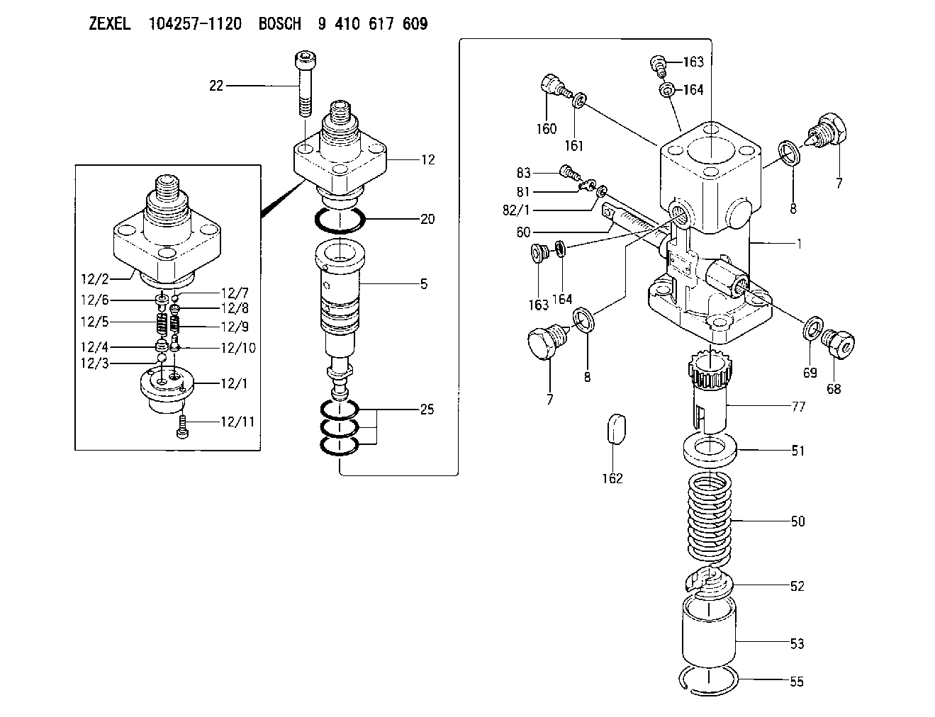
| 1. | [1] | 141053-9120 | PUMP HOUSING |
| 5. | [1] | 141185-1221 | PLUNGER-AND-BARREL ASSY |
| 7. | [2] | 141133-5401 | CAPSULE |
| 7. | [2] | 141133-5401 | CAPSULE |
| 8. | [2] | 141403-1700 | GASKET |
| 8. | [2] | 141403-1700 | GASKET |
| 12. | [1] | 141142-1121 | DELIVERY-VALVE ASSEMBLY |
| 12/1. | [1] | 141141-4200 | SEAT;D.V |
| 12/2. | [1] | 141136-9302 | FITTING |
| 12/3. | [1] | 016807-0030 | BALL |
| 12/4. | [1] | 141113-0601 | SLOTTED WASHER |
| 12/5. | [1] | 141112-7100 | COILED SPRING |
| 12/6. | [1] | 141117-9201 | FILLER PIECE |
| 12/7. | [1] | 016804-5030 | BALL |
| 12/8. | [1] | 141113-1500 | SLOTTED WASHER |
| 12/9. | [1] | 141112-8201 | COMPRESSION SPRING |
| 12/10. | [1] | 141117-9302 | FILLER PIECE |
| 12/11. | [2] | 010234-1220 | HEX-SOCKET-HEAD CAP SCREW |
| 20. | [1] | 141482-4902 | O-RING |
| 22. | [4] | 141269-1500 | BLEEDER SCREW |
| 25. | [3] | 141482-5001 | O-RING |
| 50. | [1] | 141215-6301 | COMPRESSION SPRING |
| 51. | [1] | 141216-0100 | SLOTTED WASHER |
| 52. | [1] | 141217-5100 | SLOTTED WASHER |
| 53. | [1] | 141218-8500 | GUIDE |
| 55. | [1] | 026110-6010 | LOCKING WASHER |
| 60. | [1] | 141244-9100 | CONTROL RACK |
| 68. | [1] | 141405-2100 | CAPSULE |
| 69. | [1] | 026522-2740 | GASKET D26.9&22.2T1 |
| 77. | [1] | 141241-8900 | CONTROL SLEEVE |
| 81. | [1] | 141245-2000 | POINTER |
| 82/1. | [0] | 023500-6210 | PLAIN WASHER D11&6.4T1.5 |
| 82/1. | [0] | 029300-6010 | PLAIN WASHER D11&6.4T0.8 |
| 82/1. | [0] | 029300-6020 | PLAIN WASHER D11&6.4T0.35 |
| 83. | [1] | 020006-1440 | BLEEDER SCREW M6P1L14 |
| 160. | [1] | 141418-2200 | SET OF NUTS |
| 161. | [1] | 141403-1400 | GASKET |
| 162. | [1] | 141480-1100 | COVER |
| 163. | [2] | 373658-1400 | CAPSULE |
| 163. | [2] | 373658-1400 | CAPSULE |
| 164. | [2] | 026510-1340 | GASKET D13.4&10.2T1 |
| 164. | [2] | 026510-1340 | GASKET D13.4&10.2T1 |
Cross reference number
Zexel num
Bosch num
Firm num
Name
Information:
Illustration 1 g00858201
(1) PCI Slot (2) Shared PCI/ISA Slot (3) DIMM Memory (4) Slot Cover (5) I/O Card Slot (6) CPU Slot (7) ScrewIn order to install the CPU board, perform the following procedure:
Remove the board from the anti-static packaging. Place the board on a ground, static free surface.
Illustration 2 g00858199
(8) Jumper JP2
The instructions for the board explain the locations of any jumpers or switches that need to be placed.Note: If you are replacing the CPU board, make a careful note of the cables that are attached to the existing CPU board. This will help you reconnect the cables to the new board.Note: The CPU board contains a video jumper setting that is specific to each version of the monitor. If jumper JP2 (8) is set incorrectly, the monitor video circuitry may be damaged.
Hold the board by the edges. Press the board firmly into the connector on the processor board.Note: Do not disturb the air flow director. The air flow director is required in order to keep the CPU cool. The air flow director should be routed behind the two add-in card slots. The air flow director should extend alongside the CPU heatsink.
Illustration 3 g00860148
(9) Board Retainer (10) Screw
Align the notch in the board retainer with the threaded hole. Install the screw. Hold the notch tightly against the screw before you tighten the screw.Note: Install the retainer tightly against the screw. If the retainer is not correctly installed, problems may occur when you insert an adjacent board.