Information fuel-injection pump
BOSCH
9 410 617 603
9410617603
ZEXEL
104257-1030
1042571030
DAIHATSU
E246450050Z
e246450050z
Rating:
Components :
| 0. | INJECTION-PUMP ASSEMBLY | 104257-1030 |
| 1. | _ | |
| 2. | FUEL INJECTION PUMP | |
| 3. | NUMBER PLATE | |
| 4. | _ | |
| 5. | CAPSULE | |
| 6. | ADJUSTING DEVICE | |
| 7. | NOZZLE AND HOLDER ASSY | |
| 8. | Nozzle and Holder | |
| 9. | Open Pre:MPa(Kqf/cm2) | |
| 10. | NOZZLE-HOLDER | |
| 11. | NOZZLE |
Scheme ###:
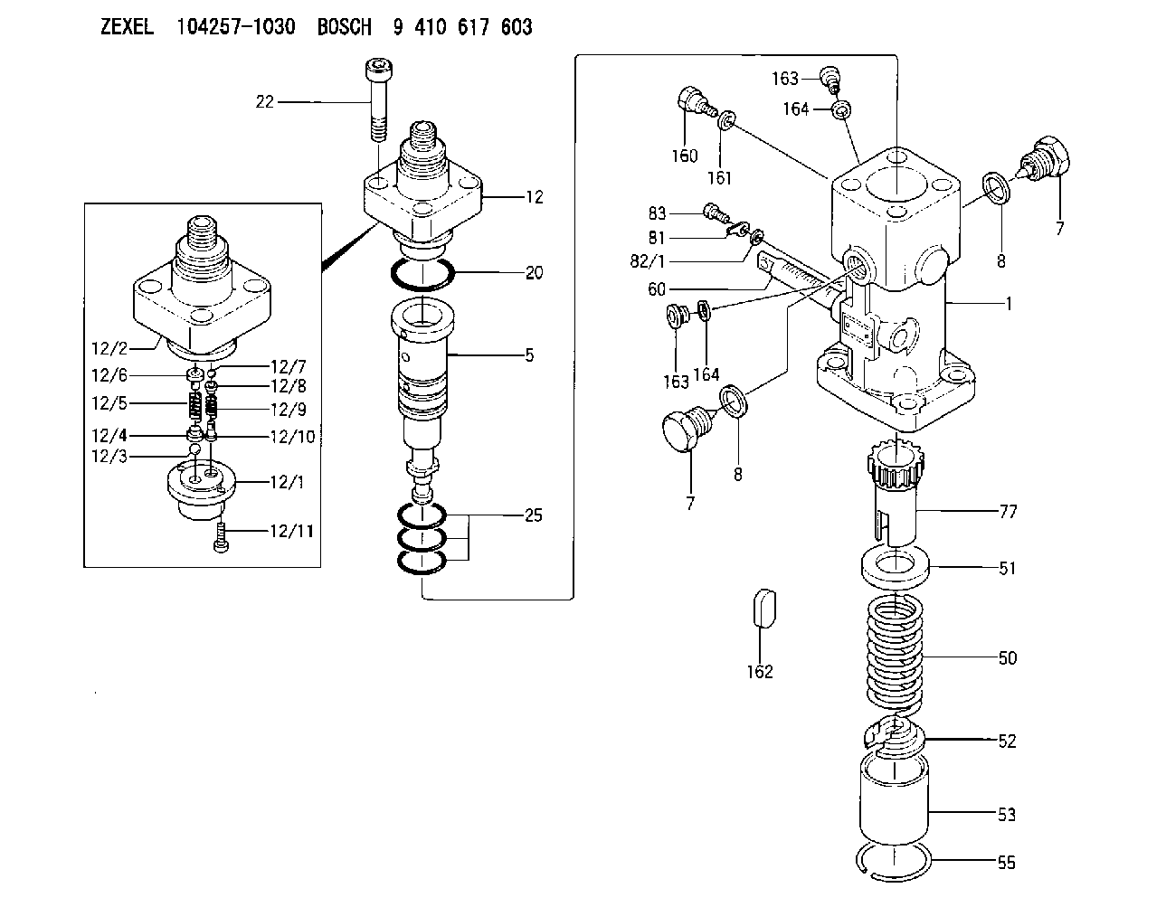
| 1. | [1] | 141054-2300 | PUMP HOUSING |
| 5. | [1] | 141185-1020 | PLUNGER-AND-BARREL ASSY |
| 7. | [2] | 141133-5401 | CAPSULE |
| 7. | [2] | 141133-5401 | CAPSULE |
| 8. | [2] | 141403-1700 | GASKET |
| 8. | [2] | 141403-1700 | GASKET |
| 12. | [1] | 141142-1121 | DELIVERY-VALVE ASSEMBLY |
| 12/1. | [1] | 141141-4200 | SEAT;D.V |
| 12/2. | [1] | 141136-9302 | FITTING |
| 12/3. | [1] | 016807-0030 | BALL |
| 12/4. | [1] | 141113-0601 | SLOTTED WASHER |
| 12/5. | [1] | 141112-7100 | COILED SPRING |
| 12/6. | [1] | 141117-9201 | FILLER PIECE |
| 12/7. | [1] | 016804-5030 | BALL |
| 12/8. | [1] | 141113-1500 | SLOTTED WASHER |
| 12/9. | [1] | 141112-8201 | COMPRESSION SPRING |
| 12/10. | [1] | 141117-9302 | FILLER PIECE |
| 12/11. | [2] | 010234-1220 | HEX-SOCKET-HEAD CAP SCREW |
| 20. | [1] | 141482-4902 | O-RING |
| 22. | [4] | 141269-1500 | BLEEDER SCREW |
| 25. | [3] | 141482-5001 | O-RING |
| 50. | [1] | 141215-6301 | COMPRESSION SPRING |
| 51. | [1] | 141216-0100 | SLOTTED WASHER |
| 52. | [1] | 141217-5100 | SLOTTED WASHER |
| 53. | [1] | 141218-8500 | GUIDE |
| 55. | [1] | 026110-6010 | LOCKING WASHER |
| 60. | [1] | 141244-9100 | CONTROL RACK |
| 77. | [1] | 141241-8900 | CONTROL SLEEVE |
| 81. | [1] | 141245-2000 | POINTER |
| 82/1. | [0] | 023500-6210 | PLAIN WASHER D11&6.4T1.5 |
| 82/1. | [0] | 029300-6010 | PLAIN WASHER D11&6.4T0.8 |
| 82/1. | [0] | 029300-6020 | PLAIN WASHER D11&6.4T0.35 |
| 83. | [1] | 020006-1440 | BLEEDER SCREW M6P1L14 |
| 160. | [1] | 141418-2200 | SET OF NUTS |
| 161. | [1] | 141403-1400 | GASKET |
| 162. | [1] | 141480-1100 | COVER |
| 163. | [2] | 373658-1400 | CAPSULE |
| 163. | [2] | 373658-1400 | CAPSULE |
| 164. | [2] | 026510-1340 | GASKET D13.4&10.2T1 |
| 164. | [2] | 026510-1340 | GASKET D13.4&10.2T1 |
Cross reference number
Zexel num
Bosch num
Firm num
Name
104257-1030
E246450050Z DAIHATSU
FUEL-INJECTION PUMP
K 24EV FUEL INJECTION PUMP PF-1WV PF
K 24EV FUEL INJECTION PUMP PF-1WV PF
104257-1030
E246450050ZA DAIHATSU
FUEL-INJECTION PUMP
A K 24EV FUEL INJECTION PUMP PF-1WV PF
A K 24EV FUEL INJECTION PUMP PF-1WV PF
104257-1030
E246450050ZC DAIHATSU
FUEL-INJECTION PUMP
B K 24EV FUEL INJECTION PUMP PF-1WV PF
B K 24EV FUEL INJECTION PUMP PF-1WV PF
Information:
Remove the single tie bolt (6) that is located in the top left corner of the pump by using Tooling (B). Refer to Illustration 7. Only remove the single tie bolt (6). Removing more bolts will result in damage to the pump.
Illustration 2 g01132938
(1) HEUI pump (2) Fuel transfer pump (4) Drive gear (5) 227-5904 O-Ring Seal (6) Tie Bolt (7) Bolts for the fuel transfer pump (8) Tie Bolts (9) Location for service bolt (12) 185-3241 O-Ring Seal
Replace tie bolt (6) with the temporary service bolt (9) that is provided in the service kit.Note: The service bolt that is provided in the kit has an undersized bolt head. The service bolt prevents the body of the HEUI pump from separating during service. Do not remove the service bolt until the fuel transfer pump has been completely reinstalled.
Tighten the service bolt (9) to 10 N m (7.4 lb ft) by using Tooling (C) .Note: Do not place an excessive torque on the service bolt. The aluminum housing of the pump could be damaged.
After installing the service bolt (9) in the top left location, remove the three bolts (7) that fasten the fuel transfer pump to the HEUI pump by using Tooling (A) .
Proceed by removing the remaining three tie bolts (8) by using Tooling (B) .
Separate the fuel transfer pump from the HEUI pump. Refer to Illustration 3.
Illustration 3 g01132944
(1) HEUI pump (2) Fuel transfer pump (9) Service bolt (10) Seals (11) SealInstalling the Fuel Transfer Pump onto the HEUI Pump
Install the two new 239-2402 Seals (10) on the back face of the HEUI pump (1). Refer to Illustration 4.
Illustration 4 g01077898
(1) HEUI pump (10) 239-2402 Seals
Install a new 179-8128 Seal (11) on the fuel transfer pump (2). Refer to Illustration 5. Use 1U-6396 O-Ring Assembly Compound in order to hold the seal in place during assembly. Ensure that the seal is completely seated.
Illustration 5 g01132957
(2) Fuel transfer pump (11) 179-8128 Seal
Do not remove the service bolt. Position the fuel transfer pump on the HEUI pump. Be sure to properly align the drive tang on the fuel transfer pump with the drive slot on the HEUI pump.Note: Align the drive tang of the fuel transfer pump so that the flat end is vertical. Refer to Illustration 5. Align the drive slot in the HEUI pump to a similar vertical orientation by using a flat head screwdriver. Refer to Illustration 6.
Illustration 6 g01132969
Note: Once the fuel transfer pump has been placed onto the HEUI pump, ensure that the face of the fuel transfer pump is flush with the face of the HEUI pump. If the pump faces are not flush, verify the alignment of the drive tang.
Install the three mounting bolts (7) for the fuel transfer pump (2). Tighten