Information fuel-injection pump
BOSCH
9 410 617 180
9410617180
ZEXEL
104256-3001
1042563001

Rating:
Components :
| 0. | INJECTION-PUMP ASSEMBLY | 104256-3001 |
| 1. | _ | |
| 2. | FUEL INJECTION PUMP | |
| 3. | NUMBER PLATE | |
| 4. | _ | |
| 5. | CAPSULE | |
| 6. | ADJUSTING DEVICE | |
| 7. | NOZZLE AND HOLDER ASSY | 105103-3490 |
| 8. | Nozzle and Holder | |
| 9. | Open Pre:MPa(Kqf/cm2) | 27.5{280} |
| 10. | NOZZLE-HOLDER | 105033-6380 |
| 11. | NOZZLE | 105011-2250 |
Scheme ###:
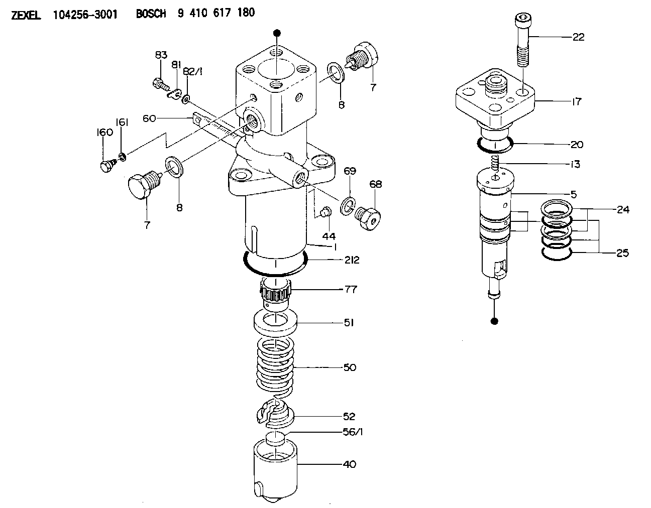
| 1. | [1] | 141055-3401 | PUMP HOUSING |
| 5. | [1] | 141189-0321 | PLUNGER-AND-BARREL ASSY |
| 7. | [2] | 141133-8500 | CAPSULE |
| 7. | [2] | 141133-8500 | CAPSULE |
| 8. | [2] | 141485-4900 | O-RING |
| 8. | [2] | 141485-4900 | O-RING |
| 13. | [1] | 141144-0600 | COMPRESSION SPRING |
| 17. | [1] | 141145-3220 | DELIVERY-VALVE ASSEMBLY |
| 20. | [1] | 141485-4800 | O-RING |
| 22. | [4] | 141269-1200 | BLEEDER SCREW |
| 24. | [2] | 016420-0400 | BACKUP RING |
| 25. | [3] | 141485-4500 | O-RING |
| 40. | [1] | 141200-3120 | TAPPET |
| 44. | [1] | 141212-0500 | BEARING PIN |
| 50. | [1] | 141215-8500 | COMPRESSION SPRING |
| 51. | [1] | 141216-6800 | SLOTTED WASHER |
| 52. | [1] | 141217-9100 | SLOTTED WASHER |
| 56/1. | [1] | 141209-2400 | PLATE T7.6 |
| 56/1. | [1] | 141209-2500 | PLATE T7.7 |
| 56/1. | [1] | 141209-2600 | PLATE T7.8 |
| 56/1. | [1] | 141209-2700 | PLATE T7.9 |
| 56/1. | [1] | 141209-2800 | PLATE T8.0 |
| 56/1. | [1] | 141209-2900 | PLATE T8.1 |
| 56/1. | [1] | 141209-3000 | PLATE T8.2 |
| 56/1. | [1] | 141209-3100 | PLATE T8.3 |
| 56/1. | [1] | 141209-3200 | PLATE T8.4 |
| 56/1. | [1] | 141209-3300 | PLATE T8.5 |
| 56/1. | [1] | 141209-3400 | PLATE T8.6 |
| 56/1. | [1] | 141209-3500 | PLATE T8.7 |
| 56/1. | [1] | 141209-3600 | PLATE T8.8 |
| 56/1. | [1] | 141209-3700 | PLATE T8.9 |
| 56/1. | [1] | 141209-3800 | PLATE T9.0 |
| 60. | [1] | 141291-4500 | CONTROL RACK |
| 68. | [1] | 141405-2100 | CAPSULE |
| 69. | [1] | 026522-2740 | GASKET D26.9&22.2T1 |
| 77. | [1] | 141241-8900 | CONTROL SLEEVE |
| 81. | [1] | 141245-2000 | POINTER |
| 82/1. | [0] | 023500-6210 | PLAIN WASHER D11&6.4T1.5 |
| 82/1. | [0] | 029300-6010 | PLAIN WASHER D11&6.4T0.8 |
| 82/1. | [0] | 029300-6020 | PLAIN WASHER D11&6.4T0.35 |
| 83. | [1] | 020006-1440 | BLEEDER SCREW M6P1L14 |
| 160. | [1] | 141418-2200 | SET OF NUTS |
| 161. | [1] | 141403-1400 | GASKET |
| 212. | [1] | 016510-8550 | O-RING |
Cross reference number
Zexel num
Bosch num
Firm num
Name
Information:
Environmental
The ambient operating temperature range is from -40° to 70°C (-40° to 158°F).
The storage temperature is from -40° to 85°C (-40° to 185°F).
The unit must be protected from direct contact with liquids. If sealing of the unit is required, the CCM must be in a water tight enclosure.
The CCM weighs 0.75 kg (1.65 lb).Mounting
The CCM can be located on a desk or on a shelf. The rubber feet on the bottom of the CCM can be removed for mounting to a panel.Note: Do not mount the CCM on the engine or within the engine mounted instrument panel. The CCM is not designed for direct engine mounting.Internal Battery
The CCM contains a battery that supplies power for internal memory whenever the CCM is turned off. Refer to the Operation and Maintenance Manual, "Battery - Replace".Power Supply
The requirements for battery voltage are 15 to 45 volts DC (24 or 32 volts DC nominal power).
The +/-B power dissipation is approximately 3.0 watts at 24 volts.
The current drawn by the CCM is 0.11 amps at 12 volts and 0.13 amps at 36 volts.
Multiple engines must share a common ground (-B).
Multiple engines must use diodes to prevent power sharing between units.Dimensions
Illustration 1 g00647099
Table 1
CCM MOUNTING DIMENSIONS
Item Dimension
A
3.5 mm (0.14 in)
B
106.5 mm (4.19 in)
C
73.0 mm (2.87 in)
D
7.5 mm (0.29 in) diameter holes (4)
E
130 mm (5.12 in)
F
149.0 mm (5.87 in)
G
66.2 mm (2.61 in)
H
125.5 mm (4.94 in)
I
17.8 mm (.70 in)