Information fuel-injection pump
BOSCH
9 410 617 593
9410617593
ZEXEL
104256-1000
1042561000
DAIHATSU
E226450030AZ
e226450030az

Rating:
Compare Prices: .
As an associate, we earn commssions on qualifying purchases through the links below

$1,717.32
31 Jul 2020
-: -
Bosch 9410617593 Fuel-Injection Pump
Components :
| 0. | INJECTION-PUMP ASSEMBLY | 104256-1000 |
| 1. | _ | |
| 2. | FUEL INJECTION PUMP | |
| 3. | NUMBER PLATE | |
| 4. | _ | |
| 5. | CAPSULE | |
| 6. | ADJUSTING DEVICE | |
| 7. | NOZZLE AND HOLDER ASSY | 105113-3251 |
| 8. | Nozzle and Holder | |
| 9. | Open Pre:MPa(Kqf/cm2) | 29.4{300} |
| 10. | NOZZLE-HOLDER | 105043-5033 |
| 11. | NOZZLE | 105011-9990 |
Scheme ###:
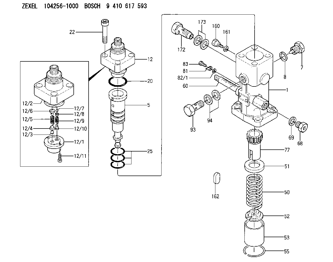
| 1. | [1] | 141053-9120 | PUMP HOUSING |
| 5. | [1] | 141185-0120 | PLUNGER |
| 7. | [1] | 141133-5401 | CAPSULE |
| 8. | [1] | 141403-1700 | GASKET |
| 12. | [1] | 141142-1121 | DELIVERY-VALVE ASSEMBLY |
| 12/1. | [1] | 141141-4200 | SEAT;D.V |
| 12/2. | [1] | 141136-9302 | FITTING |
| 12/3. | [1] | 016807-0030 | BALL |
| 12/4. | [1] | 141113-0601 | SLOTTED WASHER |
| 12/5. | [1] | 141112-7100 | COILED SPRING |
| 12/6. | [1] | 141117-9201 | FILLER PIECE |
| 12/7. | [1] | 016804-5030 | BALL |
| 12/8. | [1] | 141113-1500 | SLOTTED WASHER |
| 12/9. | [1] | 141112-8201 | COMPRESSION SPRING |
| 12/10. | [1] | 141117-9302 | FILLER PIECE |
| 12/11. | [2] | 010234-1220 | HEX-SOCKET-HEAD CAP SCREW |
| 20. | [1] | 141482-4902 | O-RING |
| 22. | [4] | 141269-1500 | BLEEDER SCREW |
| 25. | [3] | 141482-5001 | O-RING |
| 50. | [1] | 141215-6301 | COMPRESSION SPRING |
| 51. | [1] | 141216-0100 | SLOTTED WASHER |
| 52. | [1] | 141217-5100 | SLOTTED WASHER |
| 53. | [1] | 141218-8500 | GUIDE |
| 55. | [1] | 026110-6010 | LOCKING WASHER |
| 60. | [1] | 141244-9100 | CONTROL RACK |
| 68. | [1] | 141405-2100 | CAPSULE |
| 69. | [1] | 026522-2740 | GASKET D26.9&22.2T1 |
| 77. | [1] | 141241-8900 | CONTROL SLEEVE |
| 81. | [1] | 141245-2000 | POINTER |
| 82/1. | [0] | 023500-6210 | PLAIN WASHER D11&6.4T1.5 |
| 82/1. | [0] | 029300-6010 | PLAIN WASHER D11&6.4T0.8 |
| 82/1. | [0] | 029300-6020 | PLAIN WASHER D11&6.4T0.35 |
| 83. | [1] | 020006-1440 | BLEEDER SCREW M6P1L14 |
| 93. | [1] | 141402-6020 | EYE BOLT |
| 94. | [2] | 141403-1700 | GASKET |
| 160. | [1] | 141418-2200 | SET OF NUTS |
| 161. | [1] | 141403-1400 | GASKET |
| 162. | [1] | 141480-1100 | COVER |
| 172. | [1] | 141402-3320 | EYE BOLT |
| 173. | [2] | 141403-1700 | GASKET |
Cross reference number
Zexel num
Bosch num
Firm num
Name
104256-1000
E226450030AZ DAIHATSU
FUEL-INJECTION PUMP
K 24EV FUEL INJECTION PUMP PF-1WV PF
K 24EV FUEL INJECTION PUMP PF-1WV PF
104256-1000
E226450030AA DAIHATSU
FUEL-INJECTION PUMP
A K 24EV FUEL INJECTION PUMP PF-1WV PF
A K 24EV FUEL INJECTION PUMP PF-1WV PF
104256-1000
E226450030AB DAIHATSU
FUEL-INJECTION PUMP
B K 24EV FUEL INJECTION PUMP PF-1WV PF
B K 24EV FUEL INJECTION PUMP PF-1WV PF
104256-1000
E226450030AC DAIHATSU
FUEL-INJECTION PUMP
C K 24EV FUEL INJECTION PUMP PF-1WV PF
C K 24EV FUEL INJECTION PUMP PF-1WV PF
Information:
Illustration 1 g00596626
(1) Potentiometer (2) Light Emitting Diode (3) The Normally Closed Contact (4) Common Contact (5) Normally Open Contact
Preset the variable voltage power supply to 22 VDC.
Secure the variable voltage power supply.
Use the 4P-4029 Adjustment Tool to turn the potentiometer for the low voltage alarm module counterclockwise. Turn the potentiometer 25 times.
Remove the wire from the low voltage alarm module's positive terminal. Remove the wire from the low voltage alarm module's negative terminal.
Connect the power supply's positive lead to the low voltage alarm module's positive terminal.
Connect the power supply's negative lead to the low voltage alarm module's negative terminal.
Connect the multimeter to the N.O. contact and connect the multimeter to the COM contact. Set the multimeter to the function for measuring ohms. The multimeter should read "OL".
Energize the power supply.
Verify that the voltage is 22 VDC.
If the voltage is not 22 VDC, adjust the power supply.
Slowly turn the potentiometer for the low voltage alarm module clockwise until the LED illuminates.Note: The relay will energize after the LED illuminates. This occurs in 50 15 seconds.
Observe the multimeter in order to verify that the relay energized. The resistance reading should be low when the relay is energized.
Increase the output of the power supply to 24 VDC.Note: The LED and the relay de-energize simultaneously.
Remove the power supply's negative lead from the low voltage alarm module.
Remove the power supply's positive lead from the low voltage alarm module.
Remove the multimeter's leads from the low voltage alarm module.
Connect the system's wire to the low voltage alarm module's positive terminal. Connect the system's wire to the low voltage alarm module's negative terminal.