Information fuel-injection pump
BOSCH
9 410 618 064
9410618064
ZEXEL
104255-3000
1042553000
DAIHATSU
AE01064029AC
ae01064029ac

Rating:
Components :
| 0. | INJECTION-PUMP ASSEMBLY | 104255-3000 |
| 1. | _ | |
| 2. | FUEL INJECTION PUMP | |
| 3. | NUMBER PLATE | |
| 4. | _ | |
| 5. | CAPSULE | |
| 6. | ADJUSTING DEVICE | |
| 7. | NOZZLE AND HOLDER ASSY | |
| 8. | Nozzle and Holder | |
| 9. | Open Pre:MPa(Kqf/cm2) | |
| 10. | NOZZLE-HOLDER | |
| 11. | NOZZLE |
Scheme ###:
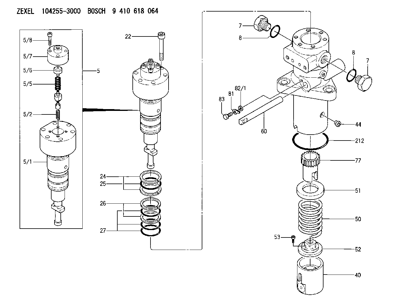
| 5. | [1] | 141189-1120 | PLUNGER-AND-BARREL ASSY |
| 5/1. | [1] | 141189-1020 | PLUNGER-AND-BARREL ASSY |
| 5/2. | [1] | 141144-2100 | COMPRESSION SPRING |
| 5/5. | [1] | 141144-2200 | COMPRESSION SPRING |
| 5/6. | [1] | 141113-5400 | SLOTTED WASHER |
| 5/7. | [1] | 141122-0000 | PLATE |
| 5/8. | [4] | 010208-3520 | HEX-SOCKET-HEAD CAP SCREW |
| 7. | [2] | 141133-8501 | CAPSULE |
| 7. | [2] | 141133-8501 | CAPSULE |
| 8. | [2] | 141485-7500 | O-RING |
| 8. | [2] | 141485-7500 | O-RING |
| 22. | [6] | 141269-1400 | BLEEDER SCREW |
| 24. | [2] | 016420-0440 | BACKUP RING |
| 25. | [1] | 141485-7300 | O-RING |
| 26. | [2] | 016420-0400 | BACKUP RING |
| 27. | [3] | 141485-7400 | O-RING |
| 40. | [1] | 141200-3920 | TAPPET |
| 44. | [1] | 141212-0500 | BEARING PIN |
| 50. | [1] | 141215-8500 | COMPRESSION SPRING |
| 51. | [1] | 141216-6800 | SLOTTED WASHER |
| 52. | [1] | 141254-3800 | SLOTTED WASHER |
| 53. | [4] | 010234-1220 | HEX-SOCKET-HEAD CAP SCREW |
| 60. | [1] | 141291-6200 | CONTROL RACK |
| 77. | [1] | 141292-5200 | CONTROL SLEEVE |
| 81. | [1] | 141245-2000 | POINTER |
| 82/1. | [0] | 023500-6210 | PLAIN WASHER D11&6.4T1.5 |
| 82/1. | [0] | 029300-6010 | PLAIN WASHER D11&6.4T0.8 |
| 82/1. | [0] | 029300-6020 | PLAIN WASHER D11&6.4T0.35 |
| 83. | [1] | 020006-1440 | BLEEDER SCREW M6P1L14 |
| 212. | [1] | 016510-8550 | O-RING |
Cross reference number
Zexel num
Bosch num
Firm num
Name
Information:
Test Procedure
System Operation
The SLC 5/04 diagnostic indicators are located on the front of the following components: Power Supply, CPU and I/O Modules.The diagnostic indicators help trace the source of the fault. Faults can be found in the following components: Input devices, Output devices, Wiring and The controller.When the red "POWER" LED is illuminated and when the green "RUN" LED is illuminated, the processor is in normal operation.If the LED indicators are illuminated and an error exists, proceed to 1.
Illustration 1 g00562937
Functional Test
Check the electrical connectors and check the wiring.
Bodily contact with electrical potential can cause bodily injury or death.To avoid the possibility of injury or death, ensure that the main power supply has been disconnected before performing any maintenance or removing any modules.
Disconnect the power supply.
Check the electrical connectors and check the wiring for damage or bad connections.
Verify that all modules are properly seated.
Verify the status of the LED on the SLC 5/04.The results of the preceding procedure are in the following list:
All of the components are fully installed. All of the components are free of corrosion. All of the components are free of damage. All of the modules are properly seated. Proceed to 2.
The components are not fully installed. The components are not free of corrosion. The components are damaged. All of the modules are not properly seated. Repair the component. Verify that the repair resolves the problem. STOP.
Replace the processor.Reference: Troubleshooting, "Processor - Replace".The results of the preceding procedure are in the following list:
The error is corrected. Stop.
Errors are displayed on the LED indicators. Follow the procedures in the Troubleshooting, "Using LED Indicators to Troubleshoot Modules". Stop.