Information fuel-injection pump
BOSCH
9 410 617 511
9410617511
ZEXEL
104254-2030
1042542030
NIIGATA-URAWA
W4H47010A
w4h47010a
Rating:
Components :
| 0. | INJECTION-PUMP ASSEMBLY | 104254-2030 |
| 1. | _ | |
| 2. | FUEL INJECTION PUMP | |
| 3. | NUMBER PLATE | |
| 4. | _ | |
| 5. | CAPSULE | |
| 6. | ADJUSTING DEVICE | |
| 7. | NOZZLE AND HOLDER ASSY | |
| 8. | Nozzle and Holder | |
| 9. | Open Pre:MPa(Kqf/cm2) | |
| 10. | NOZZLE-HOLDER | |
| 11. | NOZZLE |
Scheme ###:
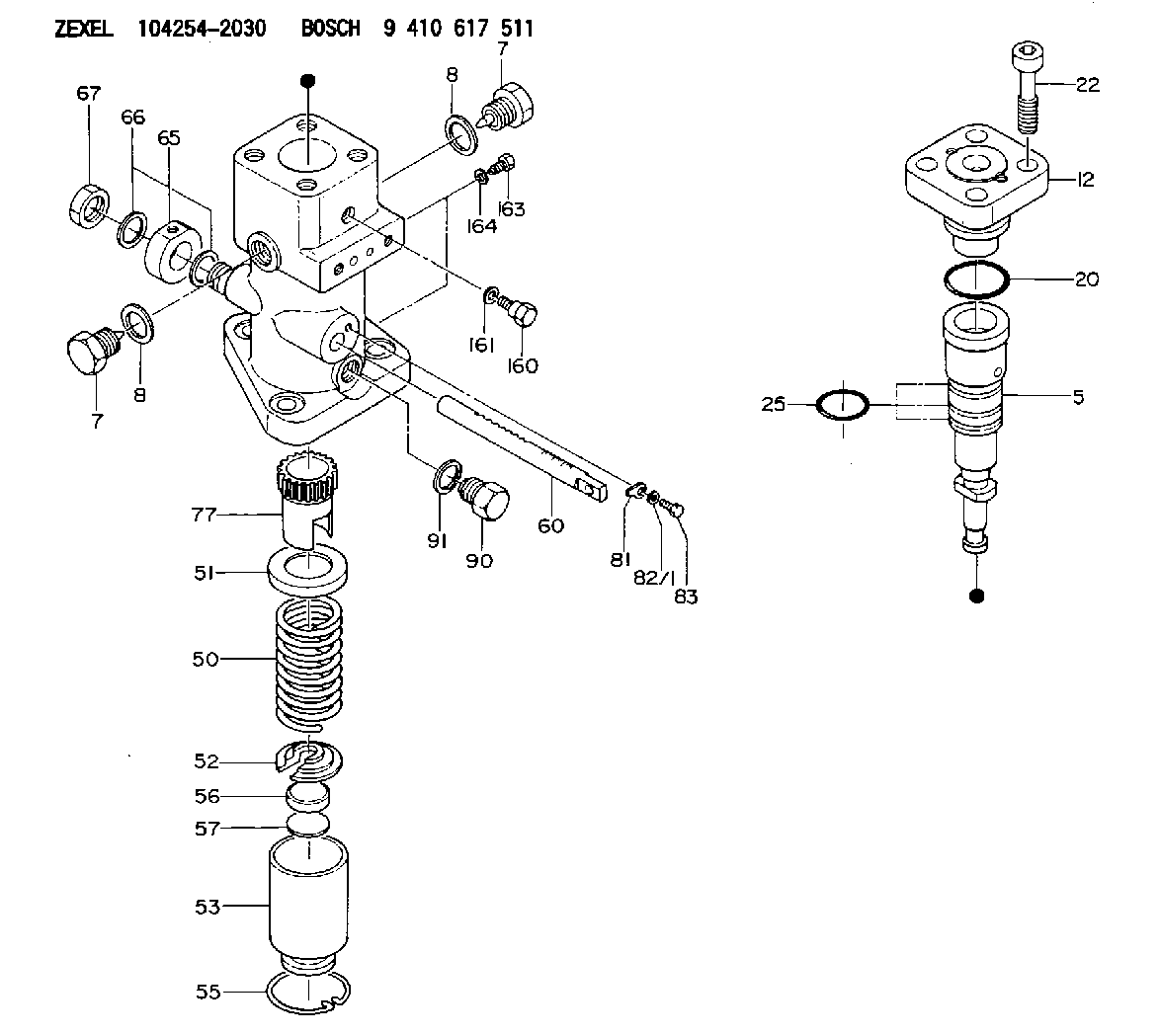
| 5. | [1] | 141186-0020 | PLUNGER-AND-BARREL ASSY |
| 7. | [2] | 141133-5400 | CAPSULE |
| 7. | [2] | 141133-5400 | CAPSULE |
| 8. | [2] | 141403-1700 | GASKET |
| 8. | [2] | 141403-1700 | GASKET |
| 12. | [1] | 141142-5320 | DELIVERY-VALVE ASSEMBLY |
| 20. | [1] | 141482-4902 | O-RING |
| 22. | [4] | 029021-6000 | HEX-SOCKET-HEAD CAP SCREW |
| 25. | [3] | 141482-5001 | O-RING |
| 50. | [1] | 141215-7501 | COMPRESSION SPRING |
| 51. | [1] | 141216-5400 | SLOTTED WASHER |
| 52. | [1] | 141217-8500 | SLOTTED WASHER |
| 53. | [1] | 141218-9620 | GUIDE |
| 55. | [1] | 141220-3000 | LOCKING WASHER |
| 56. | [1] | 141254-0200 | PLATE |
| 57. | [0] | 141209-0500 | SHIM T0.2 |
| 60. | [1] | 141291-1000 | CONTROL RACK |
| 65. | [1] | 141401-4800 | INLET UNION |
| 66. | [2] | 026524-2940 | GASKET D28.9&24.3T2 |
| 67. | [1] | 141414-0000 | CAP NUT |
| 77. | [1] | 141241-8900 | CONTROL SLEEVE |
| 81. | [1] | 141245-2000 | POINTER |
| 82/1. | [0] | 023500-6210 | PLAIN WASHER D11&6.4T1.5 |
| 82/1. | [0] | 029300-6010 | PLAIN WASHER D11&6.4T0.8 |
| 82/1. | [0] | 029300-6020 | PLAIN WASHER D11&6.4T0.35 |
| 83. | [1] | 020006-1440 | BLEEDER SCREW M6P1L14 |
| 90. | [1] | 141418-3400 | CAPSULE |
| 91. | [1] | 026522-2740 | GASKET D26.9&22.2T1 |
| 160. | [1] | 141418-2200 | SET OF NUTS |
| 161. | [1] | 141403-1400 | GASKET |
| 163. | [2] | 010006-1040 | BLEEDER SCREW M6P1L10 |
| 164. | [2] | 026506-1040 | GASKET D9.9&6.2T1 |
Cross reference number
Zexel num
Bosch num
Firm num
Name
104254-2030
W4H47010A NIIGATA-URAWA
FUEL-INJECTION PUMP
K 24EV FUEL INJECTION PUMP PF-1WV PF
K 24EV FUEL INJECTION PUMP PF-1WV PF
104254-2030
W4H47010B NIIGATA-URAWA
FUEL-INJECTION PUMP
A K 24EV FUEL INJECTION PUMP PF-1WV PF
A K 24EV FUEL INJECTION PUMP PF-1WV PF
104254-2030
W4H47010B NIIGATA-TEKKOU
FUEL-INJECTION PUMP
K 24EV FUEL INJECTION PUMP PF-1WV PF
K 24EV FUEL INJECTION PUMP PF-1WV PF
Information:
The results of the preceding procedure are in the following list:
The output corresponds to the desired pressure range. Stop.
The output does not correspond to the desired pressure range. Proceed to 3.
Calibrate the transducer. This assumes that the transducer is mounted on the engine.
Turn the isolation valve on the transducer mounting. This isolates the transducer from the engine. An arrow on the valve indicates the direction of flow. See illustration 2.
Apply a pressure that is equal to 4 mA to the transducer. See table 1. See the pressure port connection in illustration 2.
Monitor the ammeter. Adjust the zero dial until the ammeter reads 4mA. See the location of the zero dial that is in illustration 1.
Apply the pressure that is equal to 20mA to the transducer. See table 1. See the pressure port connection in illustration 2.Note: The full range of pressure may not be available. Use partial pressure. Use the highest possible pressure. This will yield the best accuracy. See table 1.
Monitor the ammeter. Adjust the zero dial until the ammeter reads 20mA. See the location of the zero dial that is in illustration 1.
Apply the pressure that is equal to 4mA to the transducer. Verify that the ammeter displays 4mA.The results of the preceding procedure are in the following list:
The output corresponds to the desired pressure range. The transducer is calibrated. Stop.
The output does not correspond to the desired pressure range. Proceed to 4.
Reapply the pressure.
Apply the pressure that is equal to 4mA to the transducer. See table 1. See the pressure port connection in illustration 2.
Monitor the ammeter. Adjust the zero dial until the ammeter reads 4mA. See the location of the zero dial that is in illustration 1.
Apply the pressure that is equal to 20mA to the transducer. See table 1. See the pressure port connection in illustration 2.Note: The full range of pressure may not be available. Use partial pressure. Use the highest possible pressure. This will yield the best accuracy. See table 1.
Monitor the ammeter. Adjust the zero dial until the ammeter reads 20mA. See the location of the zero dial that is in illustration 1.
Apply the pressure that is equal to 4mA to the transducer. Verify that the ammeter displays 4mA.The results of the preceding procedure are in the following list:Note: Repeat the procedure several times in order to properly calibrate the transducer. Continue until the 4mA signal is correct and the 20mA signal is correct.
The output corresponds to the desired pressure range. The transducer is calibrated. Stop.
The output does not correspond to the desired pressure range. Replace the transducer. Verify that the repair resolves the problem. Stop.