Information fuel-injection pump
BOSCH
F 01G 09Y 00N
f01g09y00n
ZEXEL
104254-2011
1042542011

Rating:
Components :
| 0. | INJECTION-PUMP ASSEMBLY | 104254-2011 |
| 1. | _ | |
| 2. | FUEL INJECTION PUMP | |
| 3. | NUMBER PLATE | |
| 4. | _ | |
| 5. | CAPSULE | |
| 6. | ADJUSTING DEVICE | |
| 7. | NOZZLE AND HOLDER ASSY | |
| 8. | Nozzle and Holder | |
| 9. | Open Pre:MPa(Kqf/cm2) | |
| 10. | NOZZLE-HOLDER | |
| 11. | NOZZLE |
Scheme ###:
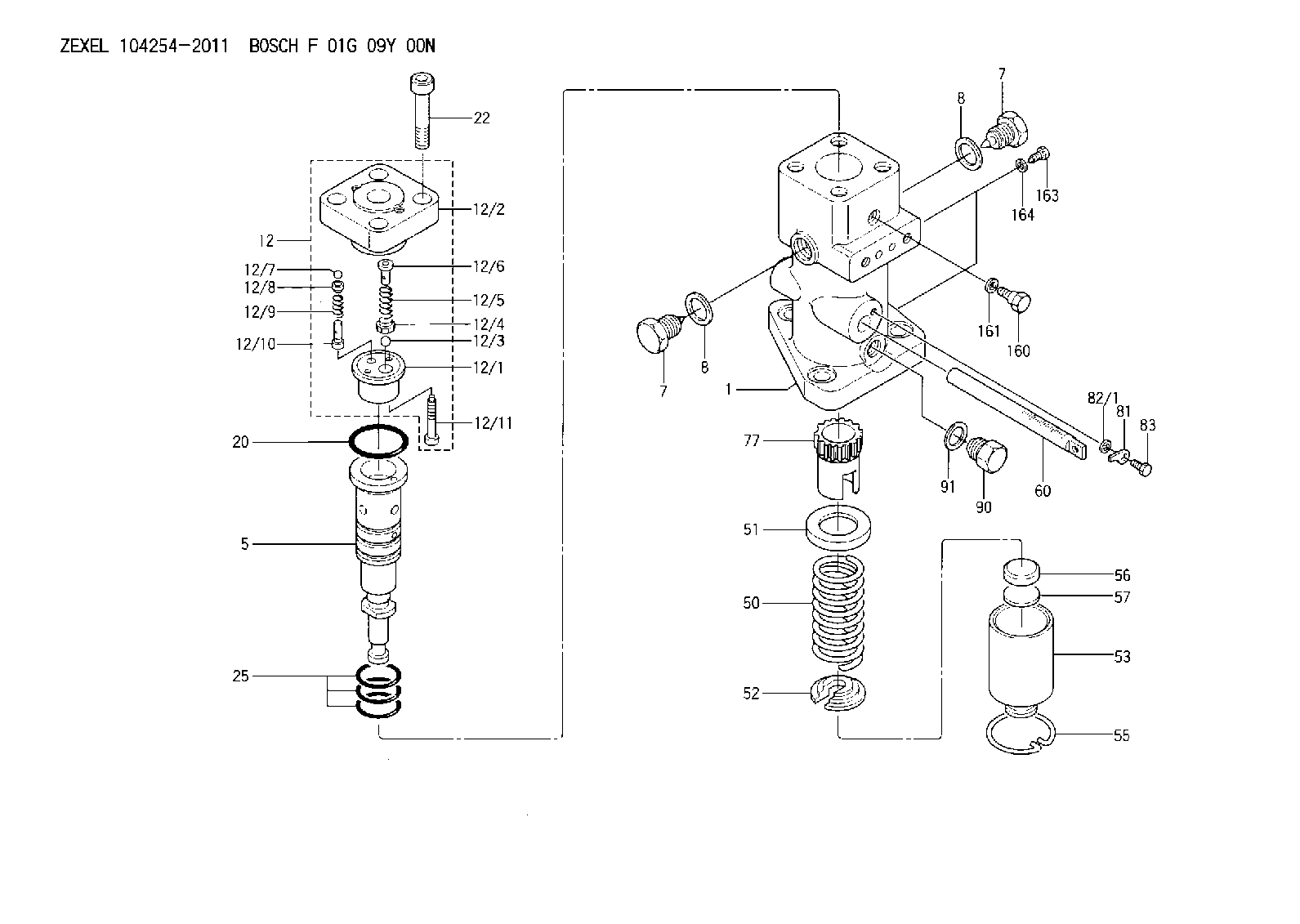
| 1. | [1] | 141054-5600 | PUMP HOUSING |
| 5. | [1] | 141186-0020 | PLUNGER-AND-BARREL ASSY WV12 |
| 7. | [2] | 141133-5401 | CAPSULE |
| 7. | [2] | 141133-5401 | CAPSULE |
| 8. | [2] | 141403-1700 | GASKET |
| 8. | [2] | 141403-1700 | GASKET |
| 12. | [1] | 141142-5320 | DELIVERY-VALVE ASSEMBLY WV2 |
| 12/1. | [1] | 141141-4200 | SEAT;D.V |
| 12/2. | [1] | 141137-4200 | FITTING |
| 12/3. | [1] | 016807-0030 | BALL |
| 12/4. | [1] | 141113-0601 | SLOTTED WASHER |
| 12/5. | [1] | 141112-7100 | COILED SPRING |
| 12/6. | [1] | 141117-9201 | FILLER PIECE |
| 12/7. | [1] | 016804-5030 | BALL |
| 12/8. | [1] | 141113-1500 | SLOTTED WASHER |
| 12/9. | [1] | 141112-8201 | COMPRESSION SPRING |
| 12/10. | [1] | 141117-9302 | FILLER PIECE |
| 12/11. | [2] | 010234-1220 | HEX-SOCKET-HEAD CAP SCREW |
| 20. | [1] | 141482-4902 | O-RING |
| 22. | [4] | 141269-1500 | BLEEDER SCREW |
| 25. | [3] | 141482-5001 | O-RING |
| 50. | [1] | 141215-7501 | COMPRESSION SPRING |
| 51. | [1] | 141216-5400 | SLOTTED WASHER |
| 52. | [1] | 141217-8500 | SLOTTED WASHER |
| 53. | [1] | 141218-9220 | GUIDE |
| 55. | [1] | 141220-3000 | LOCKING WASHER |
| 56. | [1] | 141254-0200 | PLATE |
| 57. | [0] | 141209-0500 | SHIM T0.2 |
| 60. | [1] | 141291-1000 | CONTROL RACK |
| 77. | [1] | 141241-8900 | CONTROL SLEEVE |
| 81. | [1] | 141245-2000 | POINTER |
| 82/1. | [0] | 023500-6210 | PLAIN WASHER D11&6.4T1.5 |
| 82/1. | [0] | 029300-6010 | PLAIN WASHER D11&6.4T0.8 |
| 82/1. | [0] | 029300-6020 | PLAIN WASHER D11&6.4T0.35 |
| 83. | [1] | 020006-1440 | BLEEDER SCREW |
| 90. | [1] | 141418-3400 | CAPSULE |
| 91. | [1] | 026522-2740 | GASKET |
| 160. | [1] | 141418-2200 | SET OF NUTS |
| 161. | [1] | 141403-1400 | GASKET |
| 163. | [2] | 010006-1040 | BLEEDER SCREW M6P1.0L10 |
| 164. | [2] | 026506-1040 | GASKET |
Cross reference number
Zexel num
Bosch num
Firm num
Name
Information:
Test Procedure
System Operation
An energized input closes the N.O. contacts. An energized input opens the N.C. contacts. Digital modules are used to determine whether a circuit is ON/OFF. A number of modules are available. The most common modules have sixteen channels.
Illustration 1 g00563503
Diagram of the programmable logic controller
Illustration 2 g00563591
Schematic of the discrete inputFunctional Test
Check the electrical connectors and check the wiring.
Bodily contact with electrical potential can cause bodily injury or death.To avoid the possibility of injury or death, ensure that the main power supply has been disconnected before performing any maintenance or removing any modules.
Disconnect the power supply.
Check the electrical connectors and check the wiring for damage or bad connections.
Verify that all modules are properly seated.
Verify the status of the LED on the SLC 5/04.The results of the preceding procedure are in the following list:
All of the components are fully installed. All of the components are free of corrosion. All of the components are free of damage. All of the modules are properly seated. Proceed to 2.
The components are not fully installed. The components are not free of corrosion. The components are damaged. All of the modules are not properly seated. Repair the component. Verify that the repair resolves the problem. STOP.
Verify the value of the channel.
Get on-line with the PLC.
Locate the software address for the channel.The results of the preceding procedure are in the following list:
The channel has a software address. Proceed to 3.
The channel does not have a software address. Replace the module. Verify that the repair resolves the problem. Refer to Maintenance Procedure, "Input Module and Output Module - Replace". Stop.
Apply the rated voltage.
Apply the rated voltage to the channel.
Verify that the address changed from zero to one.Note: The LED will illuminate when the rated voltage is applied to the channel.The results of the preceding procedure are in the following list:
The software address value changes. The module is functioning normally. Stop.
The software address value does not change. the module is not functioning normally. Replace the module. Verify that the repair resolves the problem. Refer to Maintenance Procedure, "Input Module and Output Module - Replace". Stop.