Information fuel-injection pump
BOSCH
9 410 617 592
9410617592
ZEXEL
104244-8072
1042448072
DAIHATSU
E206200180DZ
e206200180dz

Rating:
Components :
| 0. | INJECTION-PUMP ASSEMBLY | 104244-8072 |
| 1. | _ | |
| 2. | FUEL INJECTION PUMP | |
| 3. | NUMBER PLATE | |
| 4. | _ | |
| 5. | CAPSULE | |
| 6. | ADJUSTING DEVICE | |
| 7. | NOZZLE AND HOLDER ASSY | |
| 8. | Nozzle and Holder | |
| 9. | Open Pre:MPa(Kqf/cm2) | |
| 10. | NOZZLE-HOLDER | |
| 11. | NOZZLE |
Scheme ###:
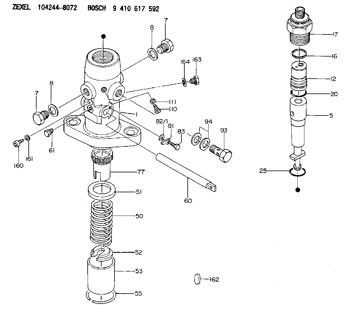
| 1. | [1] | 141054-1800 | PUMP HOUSING |
| 5. | [1] | 141175-4120 | PLUNGER-AND-BARREL ASSY |
| 7. | [2] | 141133-1500 | CAPSULE |
| 7. | [2] | 141133-1500 | CAPSULE |
| 8. | [2] | 141403-1100 | GASKET |
| 8. | [2] | 141403-1100 | GASKET |
| 12. | [1] | 141142-6121 | DELIVERY-VALVE ASSEMBLY |
| 16. | [1] | 141115-6000 | GASKET |
| 17. | [1] | 141136-7800 | FITTING |
| 20. | [1] | 029633-2040 | O-RING |
| 25. | [1] | 141482-9500 | O-RING |
| 50. | [1] | 141215-6000 | COMPRESSION SPRING |
| 51. | [1] | 141216-2400 | SLOTTED WASHER |
| 52. | [1] | 141217-6300 | SLOTTED WASHER |
| 53. | [1] | 141218-8200 | GUIDE |
| 55. | [1] | 141220-0300 | LOCKING WASHER |
| 60. | [1] | 141244-8601 | CONTROL RACK |
| 61. | [1] | 141226-4300 | BLEEDER SCREW |
| 77. | [1] | 141241-8400 | CONTROL SLEEVE |
| 81. | [1] | 141245-2000 | POINTER |
| 82/1. | [0] | 023500-6210 | PLAIN WASHER D11&6.4T1.5 |
| 82/1. | [0] | 029300-6010 | PLAIN WASHER D11&6.4T0.8 |
| 82/1. | [0] | 029300-6020 | PLAIN WASHER D11&6.4T0.35 |
| 83. | [1] | 020006-1440 | BLEEDER SCREW M6P1L14 |
| 93. | [1] | 141402-2820 | EYE BOLT |
| 94. | [2] | 141403-1300 | GASKET |
| 110. | [1] | 140420-1600 | BLEEDER SCREW |
| 111. | [1] | 141403-1200 | GASKET |
| 160. | [1] | 141418-1100 | SET OF NUTS |
| 161. | [1] | 026506-1040 | GASKET D9.9&6.2T1 |
| 162. | [1] | 141480-1100 | COVER |
| 163. | [1] | 029111-0010 | CAPSULE |
| 164. | [1] | 026510-1340 | GASKET D13.4&10.2T1 |
Cross reference number
Zexel num
Bosch num
Firm num
Name
104244-8072
E206200180DZ DAIHATSU
FUEL-INJECTION PUMP
K 24DX FUEL INJECTION PUMP PF-1CX PF
K 24DX FUEL INJECTION PUMP PF-1CX PF
Information:
Test Procedure
System Operation
The SLC 5/04 diagnostic indicators are located on the front of the following components: Power Supply, CPU and I/O Modules.The diagnostic indicators help trace the source of the fault. Faults can be found in the following components: Input devices, Output devices, Wiring and The controller.
Illustration 1 g00563535
Diagram of the LED indicators
Illustration 2 g00562937
Functional Test
Check the electrical connectors and check the wiring.
Bodily contact with electrical potential can cause bodily injury or death.To avoid the possibility of injury or death, ensure that the main power supply has been disconnected before performing any maintenance or removing any modules.
Disconnect the power supply.
Check the electrical connectors and check the wiring for damage or bad connections.
Verify that all modules are properly seated.
Connect the power supply.
Verify the status of the LED on the SLC 5/04.The results of the preceding procedure are in the following list:
All of the components are fully installed. All of the components are free of corrosion. All of the components are free of damage. All of the modules are properly seated. Proceed to 2.
The components are not fully installed. The components are not free of corrosion. The components are damaged. All of the modules are not properly seated. Repair the component. Verify that the repair resolves the problem. STOP.
Check the line voltage.
Reconnect the power supply.
Measure the line voltage at the terminals.
Verify the voltage of the power supply. The power supply voltage should be measured between 21.0 VDC and 28.0 VDC.The results of the preceding procedure are in the following list:
The line voltage is in the range. Proceed to 3.
The line voltage is out of the range. Refer to Troubleshooting, "System Power". Stop.
Attempt to operate the processor in the "RUN" mode.
Place the switch in the RUN position.The results of the preceding procedure are in the following list:
The processor enters the "RUN" mode. The processor resumes normal operation. Stop.
The processor will not enter the "RUN" mode. Proceed to 4.
Check the processor.
To avoid damage to electronic components, do not remove the processor from the SLC 5/04 Chassis until all power is removed from the power supply.Do not expose memory modules to surfaces or areas that may typically hold an electrostatic charge.
Bodily contact with electrical potential can cause bodily injury or death.To avoid the possibility of injury or death, ensure that the main power supply has been disconnected before performing any maintenance or removing any modules.
Disconnect the power supply.
Remove the processor from the chassis.
Install the processor in another chassis.
Connect the power supply.
Configure the power supply.
Attempt to operate the processor in the "RUN" mode.The results of the preceding procedure are in the following list:
The processor enters the "RUN" mode. The processor will not perform functions in the run mode. Replace the chassis. Verify that the repair solves the problem. Stop.
The processor will not enter the "RUN" mode. Replace the processor. Refer to Maintenance Procedure, "Processor - Replace".