Information fuel-injection pump
BOSCH
9 410 618 236
9410618236
ZEXEL
104244-5061
1042445061
DAIHATSU
E246400080BZ
e246400080bz

Rating:
Components :
| 0. | INJECTION-PUMP ASSEMBLY | 104244-5061 |
| 1. | _ | |
| 2. | FUEL INJECTION PUMP | |
| 3. | NUMBER PLATE | |
| 4. | _ | |
| 5. | CAPSULE | |
| 6. | ADJUSTING DEVICE | |
| 7. | NOZZLE AND HOLDER ASSY | |
| 8. | Nozzle and Holder | |
| 9. | Open Pre:MPa(Kqf/cm2) | |
| 10. | NOZZLE-HOLDER | |
| 11. | NOZZLE |
Scheme ###:
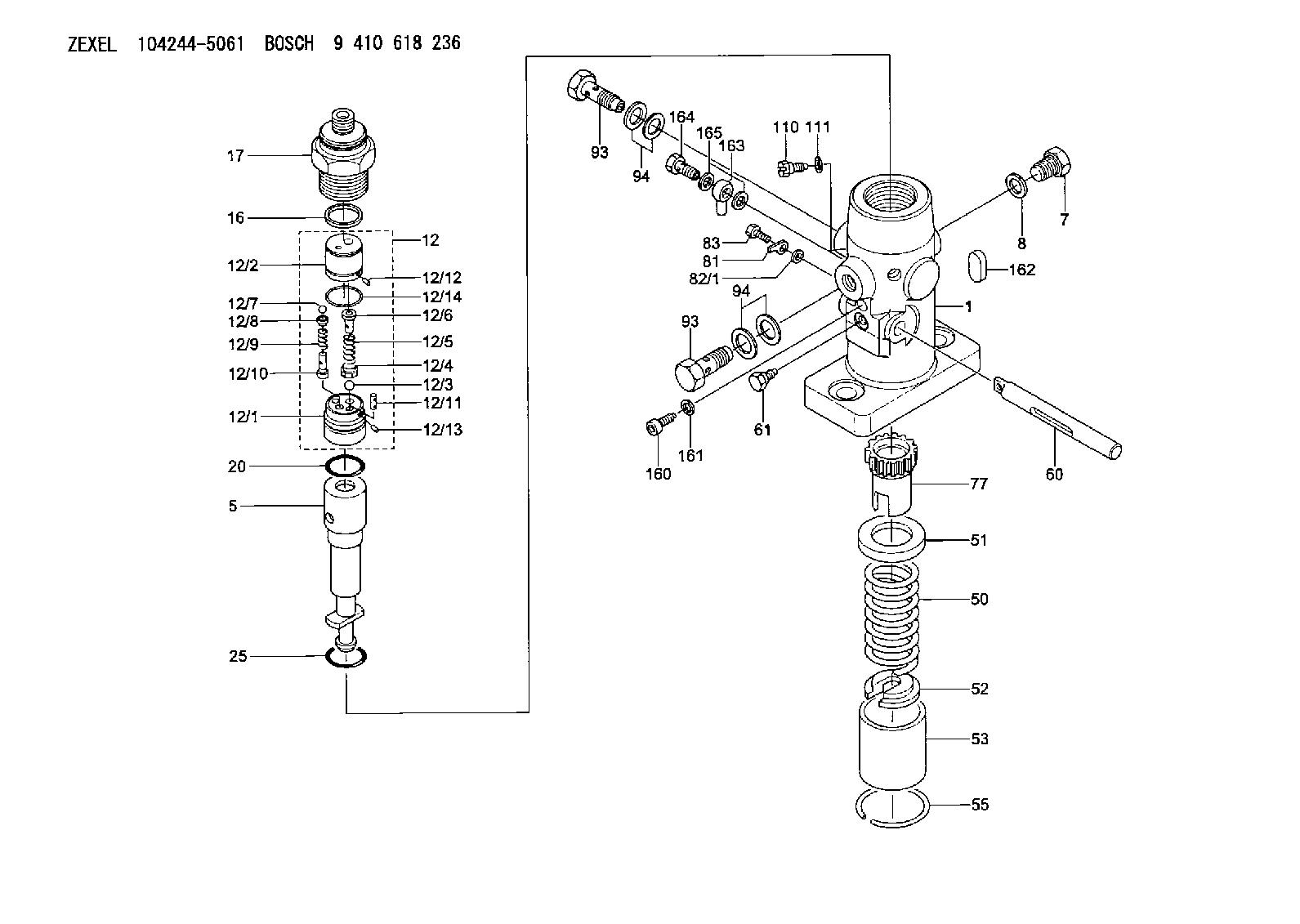
| 1. | [1] | 141053-7500 | PUMP HOUSING |
| 5. | [1] | 141175-1121 | PLUNGER-AND-BARREL ASSY C118 |
| 7. | [1] | 141133-1500 | CAPSULE |
| 8. | [1] | 141403-1100 | GASKET |
| 12. | [1] | 141142-6121 | DELIVERY-VALVE ASSEMBLY C40 |
| 12/1. | [1] | 141141-8300 | SEAT;D.V |
| 12/2. | [1] | 141141-8400 | SEAT;D.V |
| 12/3. | [1] | 016807-0030 | BALL |
| 12/4. | [1] | 141113-0601 | SLOTTED WASHER |
| 12/5. | [1] | 141112-7100 | COILED SPRING |
| 12/6. | [1] | 141117-9201 | FILLER PIECE |
| 12/7. | [1] | 016804-5030 | BALL |
| 12/8. | [1] | 141113-1500 | SLOTTED WASHER |
| 12/9. | [1] | 141112-8201 | COMPRESSION SPRING |
| 12/10. | [1] | 141117-9302 | FILLER PIECE |
| 12/11. | [2] | 141213-1400 | BEARING PIN |
| 12/12. | [2] | 141271-0200 | BEARING PIN |
| 12/13. | [2] | 029423-0080 | BEARING PIN |
| 12/14. | [1] | 141222-0400 | LOCKING WASHER |
| 16. | [1] | 141115-6000 | GASKET |
| 17. | [1] | 141136-7800 | FITTING |
| 20. | [1] | 029633-2040 | O-RING |
| 25. | [1] | 141482-9500 | O-RING |
| 50. | [1] | 141215-6000 | COMPRESSION SPRING |
| 51. | [1] | 141216-2400 | SLOTTED WASHER |
| 52. | [1] | 141217-6300 | SLOTTED WASHER |
| 53. | [1] | 141218-8200 | GUIDE |
| 55. | [1] | 141220-0300 | LOCKING WASHER |
| 60. | [1] | 141244-8700 | CONTROL RACK |
| 61. | [1] | 141226-4300 | BLEEDER SCREW |
| 77. | [1] | 141241-8400 | CONTROL SLEEVE |
| 81. | [1] | 141245-2000 | POINTER |
| 82/1. | [0] | 023500-6210 | PLAIN WASHER D11&6.4T1.5 |
| 82/1. | [0] | 029300-6010 | PLAIN WASHER D11&6.4T0.8 |
| 82/1. | [0] | 029300-6020 | PLAIN WASHER D11&6.4T0.35 |
| 83. | [1] | 020006-1440 | BLEEDER SCREW |
| 93. | [2] | 141402-2820 | EYE BOLT |
| 93. | [2] | 141402-2820 | EYE BOLT |
| 94. | [4] | 141403-1300 | GASKET |
| 94. | [4] | 141403-1300 | GASKET |
| 110. | [1] | 140420-1600 | BLEEDER SCREW |
| 111. | [1] | 141403-1200 | GASKET |
| 160. | [1] | 141418-1101 | SET OF NUTS |
| 161. | [1] | 026506-1040 | GASKET |
| 162. | [1] | 141480-1100 | COVER |
| 163. | [1] | 150948-0000 | INLET UNION |
| 164. | [1] | 141402-3720 | EYE BOLT |
| 165. | [2] | 026510-1340 | GASKET |
Cross reference number
Zexel num
Bosch num
Firm num
Name
104244-5061
E246400080BZ DAIHATSU
FUEL-INJECTION PUMP
K 24DX FUEL INJECTION PUMP PF-1CX PF
K 24DX FUEL INJECTION PUMP PF-1CX PF
104244-5061
E246400080BA DAIHATSU
FUEL-INJECTION PUMP
A K 24DX FUEL INJECTION PUMP PF-1CX PF
A K 24DX FUEL INJECTION PUMP PF-1CX PF
Information:
Input Modules
The following modules are input modules:
Thermocouple Module
RTD Input Module
Digital Modules
Analog ModulesWhen you apply a voltage to the channel, the relay is energized. An energized input will close all of the contacts that are normally open. An energized input will open all of the contacts that are normally closed. Digital modules are used to determine whether a circuit is ON/OFF. A number of modules are available. The MMS modules have sixteen channels. Discrete Output Modules
The programmable logic controller discrete output modules consist of analog modules and digital modules. Control of Voltage is provided by the output modules. A module provides power for the following list of functions: energizing the lamps, energizing the relays, energizing the fuel shutoff solenoid and energizing the air shutoff solenoid.Replacing a Module
Disconnect the power supply.
To avoid damage to electronic components, do not remove the processor from the SLC 5/04 Chassis until all power is removed from the power supply.Do not expose memory modules to surfaces or areas that may typically hold an electrostatic charge.
Press the retaining clips at the top of the module and press the retaining clips at the bottom of the module.
Remove the module from the chassis.
To avoid potential damage to the processor, handle all modules by the ends of the carrier or edges of the plastic housing. Skin oil or dirt can corrode metallic surfaces, inhibiting electrical contact.
Align the module and the guides in the chassis.
Gently slide the module in the chassis. Secure the top retainer clips and secure the bottom retainer clips.
Install a wire tie in order to secure the wiring.
Illustration 1 g00563310
Cover any unused slots. This protects the chassis.
Verify that the new module corrects the problem.