Information fuel-injection pump
ZEXEL
104242-8110
1042428110
DAIHATSU
E166450010ZZ
e166450010zz
Rating:
Components :
| 0. | INJECTION-PUMP ASSEMBLY | 104242-8110 |
| 1. | _ | |
| 2. | FUEL INJECTION PUMP | |
| 3. | NUMBER PLATE | |
| 4. | _ | |
| 5. | CAPSULE | |
| 6. | ADJUSTING DEVICE | |
| 7. | NOZZLE AND HOLDER ASSY | |
| 8. | Nozzle and Holder | |
| 9. | Open Pre:MPa(Kqf/cm2) | |
| 10. | NOZZLE-HOLDER | |
| 11. | NOZZLE |
Scheme ###:
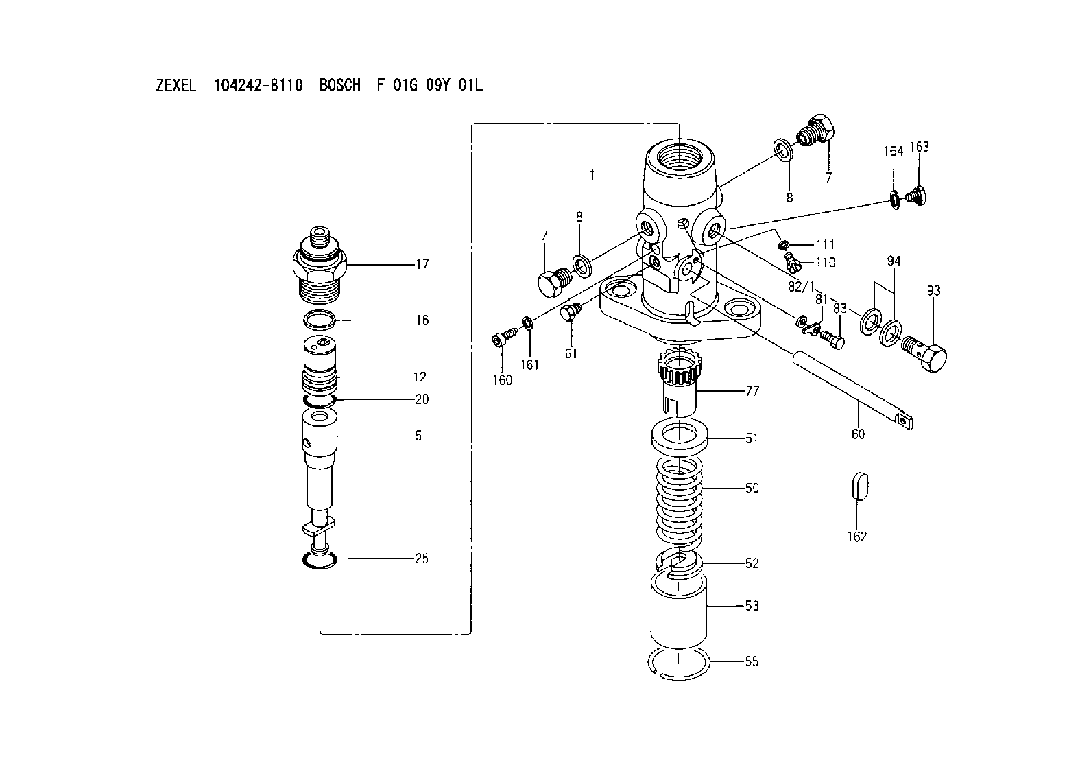
| 1. | [1] | 141054-1800 | PUMP HOUSING |
| 5. | [1] | 141175-4720 | PLUNGER-AND-BARREL ASSY D C170 |
| 7. | [2] | 141133-1500 | CAPSULE |
| 7. | [2] | 141133-1500 | CAPSULE |
| 8. | [2] | 141403-1100 | GASKET |
| 8. | [2] | 141403-1100 | GASKET |
| 12. | [1] | 141142-6121 | DELIVERY-VALVE ASSEMBLY C40 |
| 16. | [1] | 141115-6000 | GASKET |
| 17. | [1] | 141136-7800 | FITTING |
| 20. | [1] | 029633-2040 | O-RING |
| 25. | [1] | 141482-9500 | O-RING |
| 50. | [1] | 141215-6000 | COMPRESSION SPRING |
| 51. | [1] | 141216-2400 | SLOTTED WASHER |
| 52. | [1] | 141217-6300 | SLOTTED WASHER |
| 53. | [1] | 141218-8200 | GUIDE |
| 55. | [1] | 141220-0300 | LOCKING WASHER |
| 60. | [1] | 141244-8601 | CONTROL RACK |
| 61. | [1] | 141226-4300 | BLEEDER SCREW |
| 77. | [1] | 141241-8400 | CONTROL SLEEVE |
| 81. | [1] | 141245-2000 | POINTER |
| 82/1. | [0] | 023500-6210 | PLAIN WASHER D11&6.4T1.5 |
| 82/1. | [0] | 029300-6010 | PLAIN WASHER D11&6.4T0.8 |
| 82/1. | [0] | 029300-6020 | PLAIN WASHER D11&6.4T0.35 |
| 83. | [1] | 020006-1440 | BLEEDER SCREW |
| 93. | [1] | 141402-2820 | EYE BOLT |
| 94. | [2] | 141403-1300 | GASKET |
| 110. | [1] | 140420-1600 | BLEEDER SCREW |
| 111. | [1] | 141403-1200 | GASKET |
| 160. | [1] | 141418-1101 | SET OF NUTS |
| 161. | [1] | 026506-1040 | GASKET |
| 162. | [1] | 141480-1100 | COVER |
| 163. | [1] | 029111-0010 | CAPSULE |
| 164. | [1] | 026510-1340 | GASKET |
Cross reference number
Zexel num
Bosch num
Firm num
Name
Information:
Illustration 9 g00293067
(5) Air shutoff solenoid that is mounted in the air intake pipe.
Illustration 10 g00281839
Air Shutoff (Typical Example)
Table 2
(1) Air transfer pipe. (5) Air shutoff solenoid.
(2) Valve assembly. (6) O-ring seal.
(3) Shutoff shaft. (7) Diode assembly.
(4) Governor control shaft. The air shutoff solenoid (5) is located in the air inlet system on the top of the engine. When the air shutoff solenoid (ASOS) is activated, the inlet air to the engine is mechanically shut off. The ASOS can be only activated in two ways:
The ASOS is activated by the overspeed switch (OS).
The ASOS is activated by the emergency stop switch (ES).Fuel Shutoff Solenoid (FSOS)
Illustration 11 g00281970
Fuel Solenoid (Typical Example) (1) Diode assembly. (2) Spring. (3) Governor drive. (4) Fuel solenoid. (5) Shaft.
Illustration 12 g00293070
(4) Fuel shutoff solenoid (FSOS) that is mounted on the governor.The fuel shutoff solenoid (FSOS) (4) is located on the governor or on the fuel injection pump of the engine.When the FSOS is energized, the spring (2) and the shaft (5) will cause the fuel rack to move directly or the fuel rack will move through governor drive (3) to the FUEL OFF position. The FSOS remains energized until the time delay relay causes the circuit of the FSOS to de-energize.Time Delay Relay (TD)
Illustration 13 g00281989
4W-8471 Time Delay Relay The time delay relay is an ON/OFF switch which has two controls. When the electric protection system is energized, one control will immediately activate the time delay relay. The other control will activate a relay after a delay of 9 seconds when a continuous signal is received. The time delay relay has a 70 second OFF delay after the signal is removed from both the input terminal (TD-1) and the input terminal (TD-2).The time delay relay is mounted in the junction box.2301AElectric Governor Control
Illustration 14 g00293071
(1) 2301A Electric Governor Speed Control
Illustration 15 g00293069
Electric governor actuator (EGA) (2) and fuel shutoff solenoid (FSOS) (3). These components are mounted on the top of the engine.The 2301A Electric Governor Control system consists of the following components:
2301A Control
Actuator (EGA)
Magnetic pickup (MPU)The 2301A Electric Governor Control system provides precision engine speed control. The 2301A Control constantly monitors the engine rpm. The control makes necessary corrections to the engine fuel setting through an actuator connected to the fuel system.The engine rpm is measured by the magnetic pickup (MU). The magnetic pickup makes an AC voltage that is sent to the 2301A Control. The 2301A Control then sends a DC voltage signal to the actuator in order to adjust the fuel flow.The actuator changes the electrical signal from the 2301A Control to a mechanical output. The mechanical output of the actuator causes the linkage from the actuator to move the fuel rack. This will increase the flow of fuel to the engine or this will decrease the flow of fuel to the engine. For example, if the engine speed is more than the speed setting, the 2301A Control will decrease the voltage output which