Information fuel-injection pump
BOSCH
9 410 617 997
9410617997
ZEXEL
104242-8081
1042428081
DAIHATSU
E166400050AA
e166400050aa
Rating:
Components :
| 0. | INJECTION-PUMP ASSEMBLY | 104242-8081 |
| 1. | _ | |
| 2. | FUEL INJECTION PUMP | |
| 3. | NUMBER PLATE | |
| 4. | _ | |
| 5. | CAPSULE | |
| 6. | ADJUSTING DEVICE | |
| 7. | NOZZLE AND HOLDER ASSY | |
| 8. | Nozzle and Holder | |
| 9. | Open Pre:MPa(Kqf/cm2) | |
| 10. | NOZZLE-HOLDER | |
| 11. | NOZZLE |
Scheme ###:
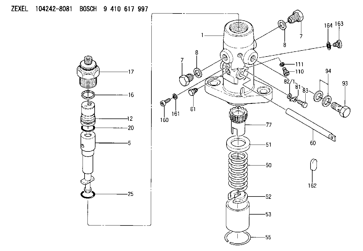
| 1. | [1] | 141054-1800 | PUMP HOUSING |
| 5. | [1] | 141175-3820 | PLUNGER-AND-BARREL ASSY |
| 7. | [2] | 141133-1500 | CAPSULE |
| 7. | [2] | 141133-1500 | CAPSULE |
| 8. | [2] | 141403-1100 | GASKET |
| 8. | [2] | 141403-1100 | GASKET |
| 12. | [1] | 141142-6121 | DELIVERY-VALVE ASSEMBLY |
| 12/1. | [1] | 141141-8300 | SEAT;D.V |
| 12/2. | [1] | 141141-8400 | SEAT;D.V |
| 12/3. | [1] | 016807-0030 | BALL |
| 12/4. | [1] | 141113-0601 | SLOTTED WASHER |
| 12/5. | [1] | 141112-7100 | COILED SPRING |
| 12/6. | [1] | 141117-9201 | FILLER PIECE |
| 12/7. | [1] | 016804-5030 | BALL |
| 12/8. | [1] | 141113-1500 | SLOTTED WASHER |
| 12/9. | [1] | 141112-8201 | COMPRESSION SPRING |
| 12/10. | [1] | 141117-9302 | FILLER PIECE |
| 12/11. | [2] | 141213-1400 | BEARING PIN |
| 12/12. | [2] | 141271-0200 | BEARING PIN |
| 12/13. | [2] | 029423-0080 | BEARING PIN |
| 12/14. | [1] | 141222-0400 | LOCKING WASHER |
| 16. | [1] | 141115-6000 | GASKET |
| 17. | [1] | 141136-7800 | FITTING |
| 20. | [1] | 029633-2040 | O-RING |
| 25. | [1] | 141482-9500 | O-RING |
| 50. | [1] | 141215-6000 | COMPRESSION SPRING |
| 51. | [1] | 141216-2400 | SLOTTED WASHER |
| 52. | [1] | 141217-6300 | SLOTTED WASHER |
| 53. | [1] | 141218-8200 | GUIDE |
| 55. | [1] | 141220-0300 | LOCKING WASHER |
| 60. | [1] | 141244-8601 | CONTROL RACK |
| 61. | [1] | 141226-4300 | BLEEDER SCREW |
| 77. | [1] | 141241-8400 | CONTROL SLEEVE |
| 81. | [1] | 141245-2000 | POINTER |
| 82/1. | [0] | 023500-6210 | PLAIN WASHER D11&6.4T1.5 |
| 82/1. | [0] | 029300-6010 | PLAIN WASHER D11&6.4T0.8 |
| 82/1. | [0] | 029300-6020 | PLAIN WASHER D11&6.4T0.35 |
| 83. | [1] | 020006-1440 | BLEEDER SCREW M6P1L14 |
| 93. | [1] | 141402-2820 | EYE BOLT |
| 94. | [2] | 141403-1300 | GASKET |
| 110. | [1] | 140420-1600 | BLEEDER SCREW |
| 111. | [1] | 141403-1200 | GASKET |
| 160. | [1] | 141418-1101 | SET OF NUTS |
| 161. | [1] | 026506-1040 | GASKET D9.9&6.2T1 |
| 162. | [1] | 141480-1100 | COVER |
| 163. | [1] | 029111-0010 | CAPSULE |
| 164. | [1] | 026510-1340 | GASKET D13.4&10.2T1 |
Cross reference number
Zexel num
Bosch num
Firm num
Name
104242-8081
E166400050AA DAIHATSU
FUEL-INJECTION PUMP
K 24DX FUEL INJECTION PUMP PF-1CX PF
K 24DX FUEL INJECTION PUMP PF-1CX PF
Information:
Introduction
Note: Do not perform any procedure in this Special Instruction until the information has been read and understood.Injector Wiring Harness Kit
The new 141-7060 Injector Wiring Harness Kit is available to repair the connectors on the 122-8835 Wiring Harness Assembly or the 133-3745 Wiring Harness Assembly . The connectors on the wiring harness assembly connect to the Hydraulic Electronic Unit Injectors (HEUI) in the above Caterpillar Truck Engines. Each injector wiring harness kit includes:
one connector
two barrel splices
two pieces of heat shrink tubingInstallation Of The 141-7060 Injector Wiring Harness Kit
Carefully remove the valve cover from the engine. Avoid damaging the gasket on the valve cover.
Remove the damaged connector from the HEUI injector solenoid.
Cut the damaged connector from the HEUI injector wiring harness. A length of 31.8 mm (1.25 inch) should remain from the heat shrink tubing on one of the harness wires. A length of 19.1 mm (0.75 inch) should remain from the heat shrink tubing on the other harness wire.Note: DO NOT allow the removed insulation to fall into the cylinder head assembly. DO NOT allow the removed insulation to fall into the open passages of the oil sump.
Remove approximately 8 mm (0.3 inch) of the insulation from the two harness wires.Note: Remove only enough insulation in order to allow the harness wires to seat into the new barrel splice from the injector wiring harness kit.
Remove the two pieces of the heat shrink tubing from the injector wiring harness kit.
Slip the heat shrink tubing from the injector wiring harness kit over the ends of the HEUI injector wiring harness wires.Note: The heat shrink tubing must be pushed far enough onto the harness wires so that the heat shrink tubing will not be cut when crimping the barrel splices. DO NOT crimp through the heat shrink tubing. Crimping through the heat shrink tubing will cause damage.
Remove the replacement connector from the injector wiring harness kit.
Install the replacement connector on the HEUI injector wiring harness wires.
Crimp the two barrel splices to the HEUI injector wiring harness wires.
Move the heat shrink tubing over the exposed barrel splices. Center the barrel splices in the heat shrink tubing.
Use a heat gun to heat the heat shrink tubing. Apply heat until the tubing shrinks evenly around the barrel splices.Note: DO NOT overheat the heat shrink tubing. Damage to the heat shrink tubing may result. The appearance of the heat shrink tubing should be uniform and smooth when properly shrunk.
Connect the repaired HEUI injector wiring harness connector to the HEUI injector solenoid.
Inspect the valve cover gasket for damage. Replace the valve cover gasket if the gasket is damaged.
Install the valve cover gasket. Install the valve cover.
Start the engine. Test the effectiveness of the repair.