Information fuel-injection pump
BOSCH
9 410 617 413
9410617413
ZEXEL
104242-0000
1042420000
Rating:
Components :
| 0. | INJECTION-PUMP ASSEMBLY | 104242-0000 |
| 1. | _ | |
| 2. | FUEL INJECTION PUMP | |
| 3. | NUMBER PLATE | |
| 4. | _ | |
| 5. | CAPSULE | |
| 6. | ADJUSTING DEVICE | |
| 7. | NOZZLE AND HOLDER ASSY | |
| 8. | Nozzle and Holder | |
| 9. | Open Pre:MPa(Kqf/cm2) | |
| 10. | NOZZLE-HOLDER | 105033-6030 |
| 11. | NOZZLE |
Scheme ###:
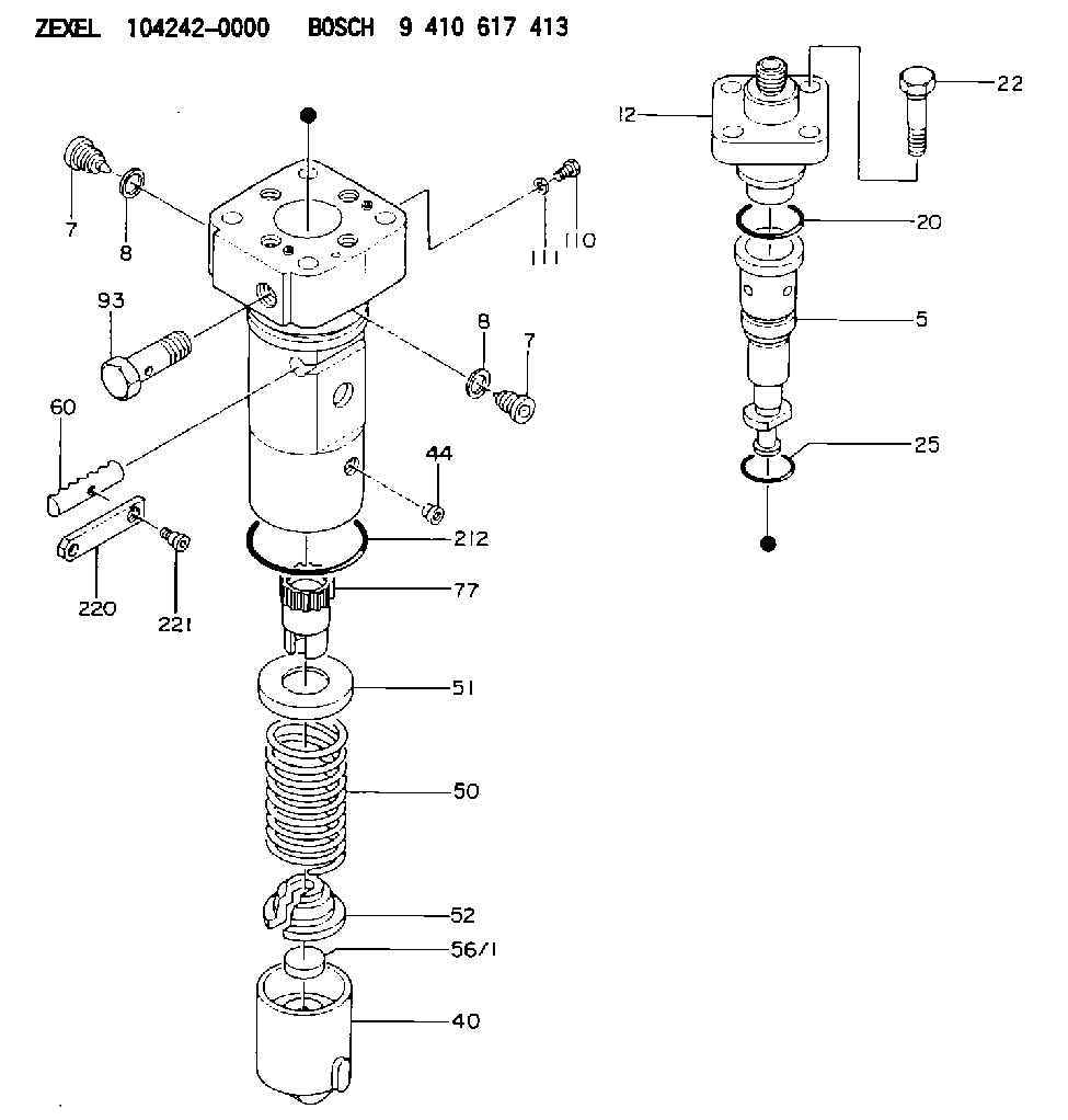
| 5. | [1] | 141185-5121 | PLUNGER-AND-BARREL ASSY |
| 7. | [2] | 141133-4701 | CAPSULE |
| 7. | [2] | 141133-4701 | CAPSULE |
| 8. | [2] | 150934-1100 | GASKET |
| 8. | [2] | 150934-1100 | GASKET |
| 12. | [1] | 141142-9720 | DELIVERY-VALVE ASSEMBLY |
| 20. | [1] | 141482-4901 | O-RING |
| 22. | [4] | 141124-1300 | BLEEDER SCREW |
| 25. | [1] | 141482-5001 | O-RING |
| 40. | [1] | 141200-2620 | TAPPET |
| 44. | [1] | 141212-0500 | BEARING PIN |
| 50. | [1] | 141215-6801 | COMPRESSION SPRING |
| 51. | [1] | 141216-4600 | SLOTTED WASHER |
| 52. | [1] | 141217-7100 | SLOTTED WASHER |
| 56/1. | [1] | 141254-1200 | PLATE T9.7 |
| 56/1. | [1] | 141254-1300 | PLATE T10.0 |
| 56/1. | [1] | 141254-1400 | PLATE T10.3 |
| 56/1. | [1] | 141254-1500 | PLATE T10.6 |
| 56/1. | [1] | 141254-1600 | PLATE T10.9 |
| 56/1. | [1] | 141254-1700 | PLATE T11.2 |
| 56/1. | [1] | 141254-1800 | PLATE T11.5 |
| 56/1. | [1] | 141254-1900 | PLATE T11.8 |
| 60. | [1] | 141244-9901 | CONTROL RACK |
| 77. | [1] | 141241-8400 | CONTROL SLEEVE |
| 93. | [1] | 141402-2100 | EYE BOLT |
| 110. | [1] | 141420-0700 | BLEEDER SCREW |
| 111. | [1] | 141403-1400 | GASKET |
| 152. | [1] | 029901-4010 | CAPSULE |
| 212. | [1] | 141482-2400 | O-RING |
| 220. | [1] | 141260-1900 | CONTROL LEVER |
| 221. | [1] | 141282-0300 | FLAT-HEAD SCREW |
Cross reference number
Zexel num
Bosch num
Firm num
Name
Information:
Image1.1.1
Image1.1.2
Image1.1.3
Image1.1.4
Image1.1.5
Image1.1.6
Image1.1.7
Image1.1.8
Image1.1.9
PROCEDURES FOR DPF MODULE REWORK
PROCEDURE ( A ) See Image 1.2.1
Butt weld ring flush to retainer ring on the inlet assembly in 4 spots.
Fillet weld (3 mm weld size) 4 tabs (at 0, 90,180 and 270 degrees.
PROCEDURE ( B ) See Image 1.2.2
Butt weld ring flush to retainer ring on the inlet assembly in 4 spots.
Fillet weld (3 mm weld size) 4 tabs (at 0, 90,180 and 270 degrees.
PROCEDURE ( C ) See Image 1.2.3
Butt weld ring flush to retainer ring on the inlet assembly in 4 spots.
Fillet weld (3 mm weld size) 4 tabs (at 0, 90,180 and 270 degrees.
PROCEDURE ( D ) See Image 1.2.4
Butt weld ring flush to retainer ring on the inlet assembly in 4 spots.
Fillet weld (3 mm weld size) 4 tabs (at 0, 90,180 and 270 degrees.
PROCEDURE ( E ) See Image 1.2.5
Butt weld ring flush to retainer ring on inlet assembly in 4 spots.
Fillet weld 2 pins (at 0 and 180 degree orientation) to outlet side of DPF's 300 mm from each other.
Drill 5/8" holes in the outlet assembly flanges 300 mm from each other.
Place tube flush to the flange inside this hole and weld to outlet assembly.
PROCEDURE ( F ) See Image 1.2.6
Position plates (at 0 and 180 degree orientation) to outlet side of the DPF flange.
Allow plates to extend ( minimum 1/4 inch ) past outer edge. Using slots in plates
weld into place.
PROCEDURE ( G ) See Image 1.2.7
Fillet weld (3 mm weld size) 2 pins (at 0 and 180 degree orientation) to outlet side of DPF 260 mm from each other.
Drill a 5/8" hole in the outlet assembly flange 260 mm from each other 13 mm deep.
Place tube flush to the flange inside this hole and weld to outlet assembly.
PROCEDURE ( H ) See Image 1.2.8
Fillet weld 2 pins (at 0 and 180 degree orientation) to outlet side of both DPF's 300 mm from each other.
Drill 5/8" holes in the outlet assembly flanges 300 mm from each other 13 mm deep.
Place tubes flush to the flange inside this hole and weld to outlet assembly.
PROCEDURE ( I ) See Image 1.2.9 and Image 1.2.10
Remove the clamp and gasket from DPF inlet side.
Mate inlet flange to DPF without gasket or clamp.
Tack weld in place.
Apply a continuous weld to the inlet flange/DPF seam.
Image1.2.1
Image1.2.2
Image1.2.3
Image1.2.4
Image1.2.5
Image1.2.6
Image1.2.7
Image1.2.8
Image1.2.9
Image1.2.10
Filter Module Cross Reference Guide See Image 1.3.1.
Image1.3.1