Information fuel-injection pump
BOSCH
9 410 617 497
9410617497
ZEXEL
104216-0060
1042160060
NIIGATA-URAWA
W0A47001A
w0a47001a
Rating:
Components :
| 0. | INJECTION-PUMP ASSEMBLY | 104216-0060 |
| 1. | _ | |
| 2. | FUEL INJECTION PUMP | |
| 3. | NUMBER PLATE | |
| 4. | _ | |
| 5. | CAPSULE | |
| 6. | ADJUSTING DEVICE | |
| 7. | NOZZLE AND HOLDER ASSY | |
| 8. | Nozzle and Holder | |
| 9. | Open Pre:MPa(Kqf/cm2) | |
| 10. | NOZZLE-HOLDER | |
| 11. | NOZZLE |
Scheme ###:
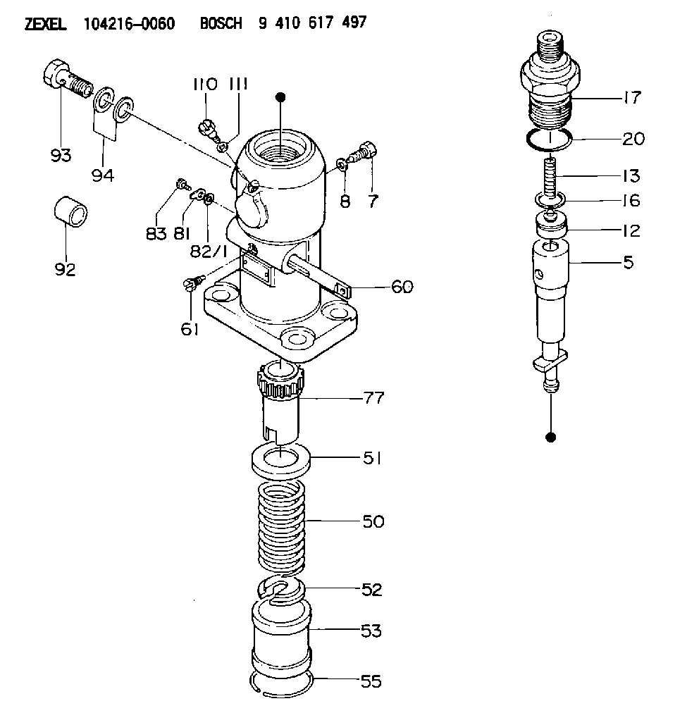
| 5. | [1] | 141171-3920 | PLUNGER-AND-BARREL ASSY |
| 7. | [1] | 141106-8300 | CAPSULE |
| 8. | [1] | 029331-2130 | GASKET |
| 12. | [1] | 141140-4220 | DELIVERY-VALVE ASSEMBLY |
| 13. | [1] | 141112-2000 | COMPRESSION SPRING |
| 16. | [1] | 141115-4600 | GASKET |
| 17. | [1] | 141126-4520 | FITTING |
| 20. | [1] | 029635-0020 | O-RING |
| 50. | [1] | 141215-2601 | COMPRESSION SPRING |
| 51. | [1] | 141216-1800 | SLOTTED WASHER |
| 52. | [1] | 141217-3000 | SLOTTED WASHER |
| 53. | [1] | 141218-5120 | GUIDE |
| 55. | [1] | 141220-1200 | LOCKING WASHER |
| 60. | [1] | 141244-3400 | CONTROL RACK |
| 61. | [1] | 141226-3200 | BLEEDER SCREW |
| 77. | [1] | 141241-2700 | CONTROL SLEEVE |
| 81. | [1] | 141245-2000 | POINTER |
| 82/1. | [0] | 023500-6210 | PLAIN WASHER D11&6.4T1.5 |
| 82/1. | [0] | 029300-6010 | PLAIN WASHER D11&6.4T0.8 |
| 82/1. | [0] | 029300-6020 | PLAIN WASHER D11&6.4T0.35 |
| 83. | [1] | 020006-1440 | BLEEDER SCREW M6P1L14 |
| 92. | [1] | 141401-2500 | BUSHING |
| 93. | [1] | 029732-6010 | EYE BOLT |
| 94. | [2] | 026526-3440 | GASKET |
| 110. | [1] | 141420-1600 | BLEEDER SCREW |
| 111. | [1] | 026506-1040 | GASKET D9.9&6.2T1 |
Cross reference number
Zexel num
Bosch num
Firm num
Name
W0A47001A NIIGATA-URAWA
FUEL-INJECTION PUMP
K 24FA FUEL INJECTION PUMP PF-1GD(V) PF
K 24FA FUEL INJECTION PUMP PF-1GD(V) PF
Information:
Caterpillar does not recommend checking actual engine bearing clearances, particularly on small engines, because of the possibility of obtaining inaccurate results, and the possibility of damaging the bearing or journal surfaces. Each Caterpillar engine bearing is quality checked for specific wall thickness. If the crankshaft journals and bores for the block and rods were measured at disassembly and found to be within specifications, no further checks are necessary when using the correct bearings. However, if the serviceman still wants to measure the bearing clearances, Plastigage is an acceptable method. Plastigage is less accurate on small diameter journals where clearances are less than 0.10 mm (0.004 in).
Lead wire, shim stock or a dial bore gauge can damage the bearing surfaces.
1. The serviceman must be very careful to use Plastigage correctly. The following points must be remembered: a. Be sure that the backs of the bearings and the bores are clean and dry.b. Be sure that the bearing locking tabs are properly seated in their studs.c. The crankshaft must be free of oil where the Plastigage touches it.d. If the main bearing clearances are checked with the engine upright or on its side, the crankshaft must be supported. Use a jack under an adjacent crankshaft counterweight and hold the crankshaft against the crown of the bearing. If the crankshaft is not supported, the weight of the crankshaft will cause incorrect readings.e. Put a piece of Plastigage on the crown of the bearing half that is in the cap. Do not allow the Plastigage to extend over the edge of the bearing.f. Install the bearing cap using the correct torque turn specifications. Do not use an impact wrench. Be careful not to dislodge the bearing when the cap is installed.g. Do not run the crankshaft with the Plastigage installed. h. Carefully remove the cap but do not remove the Plastigage. Measure the width of the Plastigage while it is in the bearing cap or on the crankshaft journal, see photograph.i. Remove all the Plastigage before reinstalling the cap. When using Plastigage, the readings can sometimes be unclear. For example, all parts of the Plastigage are not the same width. Measure the major width to be sure they are width the specification range.