Information fuel-injection pump
BOSCH
9 410 618 226
9410618226
ZEXEL
104216-0030
1042160030
NIIGATA-URAWA
10347012B
10347012b
Rating:
Components :
| 0. | INJECTION-PUMP ASSEMBLY | 104216-0030 |
| 1. | _ | |
| 2. | FUEL INJECTION PUMP | |
| 3. | NUMBER PLATE | |
| 4. | _ | |
| 5. | CAPSULE | |
| 6. | ADJUSTING DEVICE | |
| 7. | NOZZLE AND HOLDER ASSY | |
| 8. | Nozzle and Holder | |
| 9. | Open Pre:MPa(Kqf/cm2) | |
| 10. | NOZZLE-HOLDER | |
| 11. | NOZZLE |
Scheme ###:
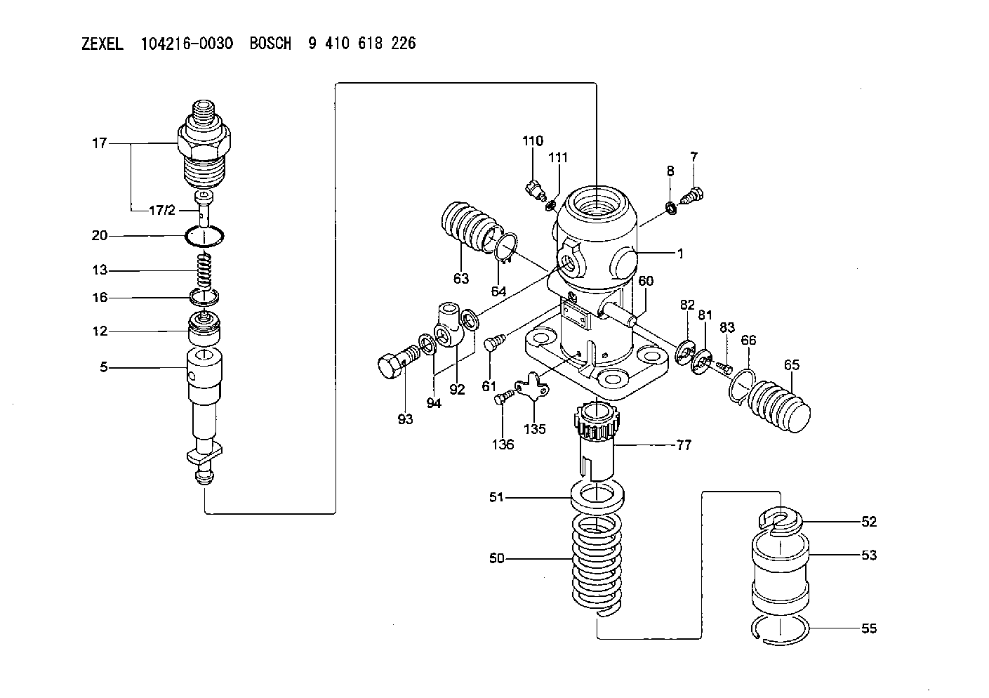
| 1. | [1] | 141052-4320 | PUMP HOUSING |
| 5. | [1] | 141171-2820 | PLUNGER-AND-BARREL ASSY |
| 7. | [1] | 141106-8300 | CAPSULE |
| 8. | [1] | 029331-2130 | GASKET |
| 12. | [1] | 141110-8120 | DELIVERY-VALVE ASSEMBLY |
| 13. | [1] | 141112-2000 | COMPRESSION SPRING |
| 16. | [1] | 141115-4600 | GASKET |
| 17. | [1] | 141126-4520 | FITTING |
| 17/2. | [1] | 141117-3800 | FILLER PIECE |
| 20. | [1] | 029635-0020 | O-RING |
| 50. | [1] | 141215-2601 | COMPRESSION SPRING |
| 51. | [1] | 141216-1800 | SLOTTED WASHER |
| 52. | [1] | 141217-3000 | SLOTTED WASHER |
| 53. | [1] | 141218-5120 | GUIDE |
| 55. | [1] | 141220-1200 | LOCKING WASHER |
| 60. | [1] | 141244-0400 | CONTROL RACK |
| 61. | [1] | 141226-3200 | BLEEDER SCREW |
| 63. | [1] | 141509-0400 | COVER |
| 64. | [1] | 141509-0700 | COILED SPRING |
| 65. | [1] | 141509-0500 | COVER |
| 66. | [1] | 141509-0600 | COILED SPRING |
| 77. | [1] | 141241-2700 | CONTROL SLEEVE |
| 81. | [1] | 141245-3400 | POINTER |
| 82. | [0] | 141246-1300 | SHIM |
| 82B. | [0] | 141246-1400 | SHIM |
| 82C. | [0] | 141246-1500 | SHIM |
| 83. | [2] | 029010-5340 | BLEEDER SCREW |
| 92. | [1] | 029702-6020 | INLET UNION |
| 93. | [1] | 029732-6010 | EYE BOLT |
| 94. | [2] | 026526-3440 | GASKET |
| 110. | [1] | 141420-1600 | BLEEDER SCREW |
| 111. | [1] | 026506-1040 | GASKET D9.9&6.2T1 |
| 135. | [1] | 141481-0020 | COVER |
| 136. | [2] | 010006-0610 | BLEEDER SCREW |
Cross reference number
Zexel num
Bosch num
Firm num
Name
104216-0030
10347012B NIIGATA-URAWA
FUEL-INJECTION PUMP
K 24FA FUEL INJECTION PUMP PF-1GD(V) PF
K 24FA FUEL INJECTION PUMP PF-1GD(V) PF
104216-0030
10347012B
FUEL-INJECTION PUMP
K 24FA FUEL INJECTION PUMP PF-1GD(V) PF
K 24FA FUEL INJECTION PUMP PF-1GD(V) PF
Information:
Start By:a. remove cylinder head assemblyb. remove oil pan 1. Remove the bolt that holds piston cooling jet (1) in position. Remove the piston cooling jet.2. Check the connecting rods and caps for their identification mark and location. The connecting rod and the rod cap should have the cylinder number etched on the right side as indicated by the arrow. If not marked, etch each unmarked connecting rod/or cap during removal.3. Remove rod cap bolts (2) and the cap from the connecting rod. Remove the lower half of the bearing from the cap. 4. Push piston and connecting rod (4) away from the crankshaft; then remove the upper half of rod bearing (5).5. Remove the piston and connecting rod from the cylinder block.6. Repeat Steps 1 through 5 for the other piston and connecting rod assemblies. The following steps are for the installation of the pistons and connecting rod assemblies.7. Put clean engine oil on the piston rings, piston in the cylinder bore. 8. Position the piston ring end gaps 120° apart. Install tool (A) to compress the rings.9. With the number one crankshaft throw at bottom center, install the piston and connecting rod. Some engines use pistons which have the word "FRONT" stamped on the crown of the piston. Be sure the word "FRONT" is toward the front of the engine when the piston is installed. The etched number on the connecting rod must be on the right side and must be installed in the corresponding cylinder.10. Line up the connecting rod with the crankshaft. Using a soft faced hammer, carefully tap the piston into the cylinder bore until tooling (A) comes off of the piston.11. Before the connecting rod comes in contact with crankshaft, install the upper half of the rod bearing. Be sure the bearing tab properly engages with the slot in the connecting rod.12. Put clean engine oil on the upper rod bearing surface. Using a soft faced hammer, tap the piston down while guiding the connecting rod onto the crankshaft.13. Position the lower half of the rod bearing in the corresponding numbered rod cap. Be sure the bearing tab engages with the grove in the rod caps.14. Put clean engine oil on the lower rod bearing surface; then install the rod cap. Install the bearing cap on the connecting rod with the number on the bearing (rod) cap on the same side and same number as on the connecting rod.15. Put 2P2506 Thread Lubricant on the threads of rod cap bolts (1) and the seating surfaces of the caps. Install rod cap bolts (1). Tighten them to a torque of 130 7 N m (95 5 lb ft). Mark each bolt head, and then tighten each rod cap bolt an additional 1/6 60 5 ( turn).16. Repeat Steps 7 through 15 for the remainder of the piston and connecting rods.17. Reinstall piston cooling jets (1).End By:a. install oil panb. install cylinder head assemblyDisassemble & Assemble Piston & Connecting Rod Assemblies
Start
Start